
In this blog, we have step by step guide to calibrating the APM 2.8 flight controller using Mission Planner.

In this tutorial, we will be using –
- APM 2.8 flight controller – see here
- FlySky FS-i6 2.4G 6CH PPM RC Transmitter With FS-iA6B Receiver
- Q450 Quadcopter Frame – PCB Version Frame Kit with Integrated PCB
- 2212 920KV Brushless DC Motor for DJI
- Orange HD Propellers
- DYS 30A Brushless Speed Controller ESC
- Orange 3000mAh 3S 40C/80C Lithium polymer battery Pack (LiPo)
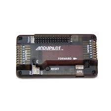
APM 2.8 Flight Controller
The APM 2.8 Multicopter Flight Controller is completely an open-source autopilot system that can control Planes, Copters, and Rovers. These are professional quality IMU autopilots based on the Arduino Mega platform. It allows the user to turn any fixed, rotary-wing, in addition, it is capable of turning the multirotor vehicle into a fully autonomous vehicle. Moreover, it performs programmed GPS missions with waypoints.
Calibrating the APM 2.8 Flight Controller using Mission Planner.
Step 1 – Installing Mission Planner and Connecting with APM
- MissionPlanner is a free open source (Windows only) application that acts as a virtual ground control station for your drone, plane, or rover. The software allows you to customize your autonomous device’s settings and assure top performance. Mission Planner is available for download here.http://ardupilot.org/planner/docs/mission-planner-installation.html OR you click here to download directly
- APM and Pixhawk flight controllers can be programmed with it.
- When you connect your APM flight controller to your computer using a USB to MicroUSB cable, a green led will illuminate and a red led will begin blinking.
- The PC will recognize the board as an “Arduino Mega” and will install the necessary drivers automatically.
- Open the Mission Planner software and choose the appropriate COM port in the upper right corner at a baud rate115200
- Don’t select on connect yet on the top right corner.
- Now select the type of Multirotor configuration from the “INITIAL SETUP” tab and click “Install Firmware.” We’ll choose a quadrotor arrangement here. Continue by granting additional permissions, and the firmware update will begin.

- Booting the Firmware to the APM board will take about 2-3 minutes ( Make Sure your PC is connected to the internet as it will be downloading some required files ).
- After that, click CONNECT in the top right corner of the window to connect the APM board to the computer.
- The Device will now be listed as “Quadrotor.”

Step 2 – Calibrating Compass and Accelerometer
- Now again go to the Initial Setup tab and click on Mandatory Hardware.

- To begin, choose a frame type for your Quadcopter and then the X type of frame.

- Now go to the Accel Calibration Section and click on Calibrate Accel.

- To calibrate the Accelerometer, follow the on-screen directions and do the same.
- After you’ve finished calibrating the accelerometer, you can move on to calibrating the compass.
- There is no need for an external compass with APM 2.8 because it has one built-in compass.
- Simply go to Live Calibration and begin spinning your APM 3600.


- When you’re finished, click Finish.
- Go to the flight data tab in the top right corner to see it graphically.
- While the APM is connected to Mission Planner, move it. You’ll be able to monitor the change in flight position as well as the corresponding values.

Step 3 – Connecting and Calibrating Radio Control
- We’ll need to link Reciever to the Flight Controller for this.
- The pin arrangement of the APM’s input side (which is to be connected to the APM) and the Reciever FS-iA6 are as illustrated.
- APM 2.5, 2.6, and 2.8 all have equal levels of confidence. The ground is on the outermost pin, Positive is on the middle pin, and the Signal is on the innermost pin.
- The best technique to connect several channels to the receiver is also demonstrated.

- The PinOut for the FS-iA6 Reciever is shown below. The first channel controls ROLL/AILERON, the second controls PITCH/ELEVATOR, the third controls THROTTLE, the fourth controls YAW/RUDDER, and the fifth and sixth controls Mode selection.
- The outer switch is a Negative switch, the middle switch is a Positive switch, and the left or innermost switch is a signal pin.
- The other 6 Channel Receivers have a similar channel arrangement.

- Now Connect the transmitter to the receiver. We’ll link APM and Reciever in this section.
- For connection, use the image below as a guide.

- A red light will now illuminate in the Receiver, indicating that the connection has been established. Ascertain that the Reciever is connected to the Transmitter.
- Now, in the Mandatory Hardware section, proceed to the Radio Calibration section.

- For each parameter, you’ll see a different bar. The bar for the associated parameter will now change if you move any stick on the transmitter’s joystick.
- Select the calibrate radio button and adjust all of the parameters to the extremes. Change the position of the knobs to extreme and move the joystick in all directions.
- You’ll see that the Mission Planner will now collect Red extreme lines for the respective channels. Now, because the extremes will be taken by software, click the “save when done” button to save the results.

Now the Calibration is done, and your APM is now programmed to fly. Now you need to do Connections of APM with ESCs, which will then be connected to Motors.
Conclusion:
I hope all of you are clear about how to calibrate the APM 2.8 flight controller using Mission Planner. We MATHA ELECTRONICS will be back soon with more interesting topics.