
We are discussing another interfacing technique in this tutorial. This time, we’re connecting an Arduino to an RFID reader that can scan RFID tags. Radio Frequency Identification, or RFID. RFID tags are read using an RFID reader (which contains certain unique data stored in a chip). A coil surrounds both an RFID reader and an RFID tag. An RFID reader takes the unique tag data—a string of digits and characters—from an RFID tag when it is placed close to the reader.
Due to RFID technology, the days of waiting in lengthy grocery store checkout lines are long gone. You can load up your cart and head out the door with an RFID-based walk-through automatic checkout solution. The RFID tags that are now affixed to the items allow for almost quick detection and ringing of every item in the cart, eliminating the need for you to wait for someone to ring each one individually.
What is RFID?
Radio waves are essentially used by RFID, or radio frequency identification, to read the data on tags. The embedded transmitter and receiver are part of the RFID tags, which are connected to objects. Fast and requiring no physical touch between the reader and the tag, RFID tags can be read from several feet away.
An RFID system consists of two parts: Tag and Reader
- RFID Tag
An RFID tag has an antenna for receiving and transmitting signals as well as a chip for storing data about a physical object. A typical RFID tag may hold 1KB of data, which is sufficient to retain the user’s name, credit card number, unique identification number, date of birth, and more data.
- RFID Reader
The RFID reader may both transmit and receive information. So, a transceiver is another way to phrase it. An antenna, radio frequency module, and control unit are all parts of the RFID reader.
RFID WORKING
When a tag approaches an RFID reader that produces a high-frequency electromagnetic field, induction causes a voltage to be induced in the tag’s antenna coil. The tag is powered by this induced voltage. In response, the tag changes the signal’s power and communicates with the reader.

RC522 RFID module
One of the cheapest RFID alternatives you can get online is the RC522 RFID module based on the MFRC522 IC from NXP. A key fob tag with 1KB of memory and an RFID card tag is typically included. The finest thing is that you can save any message in it because it has the ability to write a tag.

A 13.56MHz electromagnetic field is produced by the RC522 RFID reader module in order to communicate with RFID tags (ISO 14443A standard tags). With a maximum data rate of 10 Mbps, the reader may interface with a microcontroller using a 4-pin SPI connector. Additionally, it supports the I2C and UART protocols for communication.
The good news is that though the module’s operational voltage spans from 2.5 to 3.3V, the logic pins are 5-volt tolerant, allowing us to connect it directly to an Arduino or other 5V logic microcontroller without the need for a logic level converter.
Technical Specifications
- Integrated MFRC522 module 13.56MHz RFID module
- Operating voltage: 2.5V to 3.3V
- Supports SPI, I2C protocol, UART communication
- Maximum data rate: 10Mbps
- Read range: 5cm
- Current consumption: 13-26 mA
- Power down mode consumption: 10mA
- Low cost and low voltage device
- Advanced modulation and demodulation concepts are completely integrated into all types of 13.56MHz passive contactless communication methods and protocol
- 14443A compatible transponder signal
- Can be directly loaded into various reader molds
- Dimension: 12.3*11.9*3.8cm
- Weight: 20gm
Connection
| RFID-RC522 PIN | ARDUINO UNO PIN |
| SDA | 10 |
| SCK | 13 |
| MOSI | 11 |
| MISO | 12 |
| IRQ | UNUSED |
| GND | GND |
| RST | 9 |
| 3.3 V | 3.3 V |
RC522 RFID Reader/Writer Module Pinout
There are 8 pins altogether on the RC522 module. Each pin on this module has a different purpose for each of the communication protocols that it supports. An RFID Reader module’s pinout is as follows:
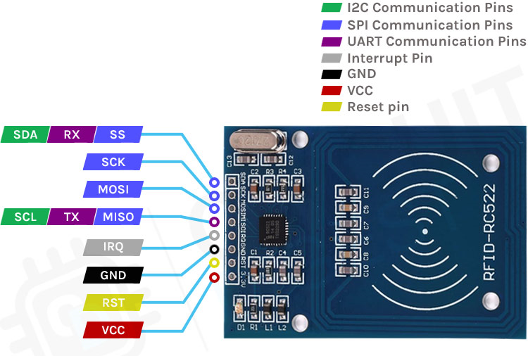
- SDA SCL: I2C Communication pins. DATA and CLOCK.
- SS SCK MOSI MISO: SPI communication pins. Slave Select, Clock, MOSI, and MISO.
- RX TX: UART Communication pins.
- IRQ: Interrupt signal from the module to indicate RFID tag detection.
- GND: Ground pin that needs to be connected to the GND pin on the Arduino.
- RST: Reset pin for the module
- VCC: Supply pin for the module. The supply voltage can be anywhere from 2.5V to 3.3V and must be connected to the 3.3V pin on the Arduino.
RC522 RFID Reader/Writer Module Circuit Diagram
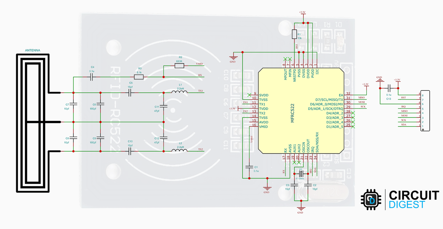
The RC522 module’s schematic diagram is provided below. The circuit only has the bare necessities. The MFRC522 chip is the primary element, as we are all aware. Together with the antenna matching circuit, the remaining parts make up the EMI filter.
How is the RFID Works?
The RFID system is comprised of two components: the RFID reader and the tags. They are also called PCD (Proximity Coupling Device) and PICC (Proximity Integrated Circuit Card).
The RFID reader consists of an antenna to emit high-frequency EM waves and a reader/writer. MFRC522 from NXP is an example of such an integrated circuit. Since we are using high-frequency waves in the megahertz range, the size of the antenna can be small.

RFID tags come in passive and active varieties. While passive RFID tags are powered by energy from the reader’s interrogating EM waves, active tags are powered by batteries. Cards, tags, key chains, and stickers are just a few of the various shapes and forms that the tags might take. Whatever its form, an antenna plus an RFID chip that stores all the data make up an RFID tag.
The tag will transmit information back to the reader when it receives an electromagnetic interrogation pulse from a nearby RFID reader. In order to identify the tag, the reader will then examine this data. The tag does not need to be in the reader’s line of sight, unlike a barcode or a QR code. This makes it easier to process and can be used for tracking objects in closed space.
RC522 RFID Reader Module

The MFRC522 supports three different communication protocols:
- SPI with Speed up to 10Mbit/s
- I2C interface with speed up to 400kBd in Fast mode and up to 3400kBd in High-Speed mode
- RS232 Serial UART with speed up to 1228.8kBd
Typically, the RC522 module includes a key fob and an RFID card. Additionally, each of these has 1KB of memory. With the RC522 module, we are able to program these tags in addition to reading them. This image displays the tags and the RC522 module together.
Arduino RC522 RFID Reader Interfacing Circuit Diagram
For interfacing the RC522 RFID module with the Arduino, we will be using the SPI interface. Follow the circuit diagram and make the connections as per that.
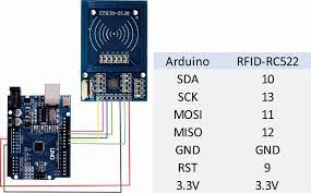
The 3.3V and GND pins of the Arduino are connected, respectively, to the VCC and GND pins of the module. The Arduino’s D9 pin serves as the Reset pin, and the D10, D11, D12, and D13 pins serve as the SS, MOSI, MISO, and SCK pins, respectively. The SS and RST pins of the Arduino are programmable and can be connected to any other digital pins.
Arduino RC522 RFID Module Code
Let’s look at the coding portion as the connections are made. We’ll do it by utilizing Miguel André Balboa’s MFRC522 Arduino Library. Download the library from the MFRC522 GitHub repository and install it in the Arduino library folder since it isn’t listed in the Arduino library manager. You can install it using the Arduino IDE, by selecting the downloaded.ZIP file under Sketch -> Include Library -> Add ZIP Library, or by simply extracting the Zip file into the Arduino library folder.
Once the library is installed, we can use some sample code to test our configuration. Open the MFRC522 library’s DumpInfo example for that. Here is a sample of the code.
#include <SPI.h> #include <MFRC522.h> #define RST_PIN 9 // Configurable, see typical pin layout above #define SS_PIN 10 // Configurable, see typical pin layout above MFRC522 mfrc522(SS_PIN, RST_PIN); // Create MFRC522 instance void setup() { Serial.begin(115200); // Initialize serial communications with the PC while (!Serial); // Do nothing if no serial port is opened (added for Arduinos based on ATMEGA32U4) SPI.begin(); // Init SPI bus mfrc522.PCD_Init(); // Init MFRC522 delay(4); // Optional delay. Some board do need more time after init to be ready, see Readme mfrc522.PCD_DumpVersionToSerial(); // Show details of PCD – MFRC522 Card Reader details Serial.println(F(“Scan PICC to see UID, SAK, type, and data blocks…”)); } void loop() { // Reset the loop if no new card present on the sensor/reader. This saves the entire process when idle. if ( ! mfrc522.PICC_IsNewCardPresent()) { return; } // Select one of the cards if ( ! mfrc522.PICC_ReadCardSerial()) { return; } // Dump debug info about the card; PICC_HaltA() is automatically called mfrc522.PICC_DumpToSerial(&(mfrc522.uid)); } |
Open the serial monitor and display any tag close to the RC522 module once it has been assembled and uploaded to the Arduino. The reader will read every bit of information from the tag when it is nearby and dump it into the serial monitor as seen below.
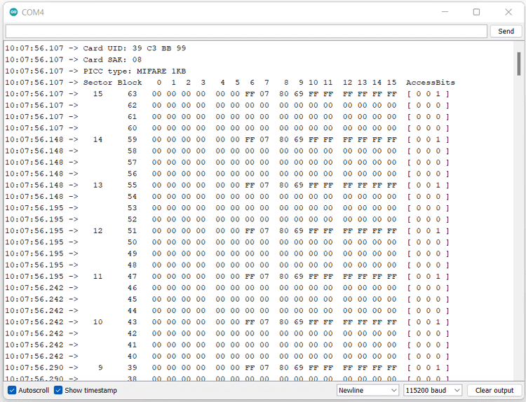
All the information, including the card’s UID, SAK, PICC type, and memory maps, will be included in the data dump. As the name implies, the UID, or Unique ID, is distinct for each tag. Our serial baud rate is too sluggish, which is the cause of any communication failure errors you may encounter. The problem can be fixed by changing the code’s baud rate to 115200. We can see that the PICC type is MIFARE 1KB in this data dump. This indicates that a MIFARE chip with 1KB of memory is present in the tag.
Writing data to the RFID tag
Let’s look at how we may write some data to the card now that we have extracted the factory data from the tag. Use the following code to achieve that.
#include <SPI.h> //include the SPI library #include <MFRC522.h> //include the MFRC522 RFID reader library #define RST_PIN 9 //reset pin, which can be changed to another digital pin if needed. #define SS_PIN 10 //SS or the slave select pin, which can be changed to another digital pin if needed. MFRC522 mfrc522(SS_PIN, RST_PIN); // create a MFRC522 instant. MFRC522::MIFARE_Key key; //create a MIFARE_Key struct named ‘key’ to hold the card information byte data1[14] = {“Circuit-Digest”}; //The first data that needs to be written to the tag. byte data2[12] = {“Jobit-Joseph”}; //The second data that needs to be written to the tag. byte readbackblock[18]; //Array for reading out a block. void setup() { Serial.begin(115200); // Initialize serial communications with the PC SPI.begin(); // Init SPI bus mfrc522.PCD_Init(); // Init MFRC522 card (in case you wonder what PCD means: proximity coupling device) Serial.println(“Scan a MIFARE Classic card”); for (byte i = 0; i < 6; i++) { key.keyByte[i] = 0xFF; // Prepare the security key for the read and write operations. } } void loop() { // Look for new cards if not found rerun the loop function if ( ! mfrc522.PICC_IsNewCardPresent()) { return; } // read from the card if not found rerun the loop function if ( ! mfrc522.PICC_ReadCardSerial()) { return; } Serial.println(“card detected. Writing data”); writeBlock(1, data1); //write data1 to the block 1 of the tag writeBlock(2, data2); //write data2 to the block 2 of the tag Serial.println(“reading data from the tag”); readBlock(1, readbackblock); //read block 1 //print data Serial.print(“read block 1: “); for (int j = 0 ; j < 14 ; j++) { Serial.write (readbackblock[j]); } Serial.println(“”); readBlock(2, readbackblock); //read block 2 //print data Serial.print(“read block 2: “); for (int j = 0 ; j < 12 ; j++) { Serial.write (readbackblock[j]); } Serial.println(“”); //mfrc522.PICC_DumpToSerial(&(mfrc522.uid));//uncomment below line if want to see the entire memory dump. } //Write specific block int writeBlock(int blockNumber, byte arrayAddress[]) { //check if the block number corresponds to data block or triler block, rtuen with error if it’s trailer block. int largestModulo4Number = blockNumber / 4 * 4; int trailerBlock = largestModulo4Number + 3; //determine trailer block for the sector if (blockNumber > 2 && (blockNumber + 1) % 4 == 0) { Serial.print(blockNumber); Serial.println(” is a trailer block: Error”); return 2; } //authentication byte status = mfrc522.PCD_Authenticate(MFRC522::PICC_CMD_MF_AUTH_KEY_A, trailerBlock, &key, &(mfrc522.uid)); if (status != MFRC522::STATUS_OK) { Serial.print(“Authentication failed: “); Serial.println(mfrc522.GetStatusCodeName(status)); return 3;//return “3” as error message } //writing data to the block status = mfrc522.MIFARE_Write(blockNumber, arrayAddress, 16); //status = mfrc522.MIFARE_Write(9, value1Block, 16); if (status != MFRC522::STATUS_OK) { Serial.print(“Data write failed: “); Serial.println(mfrc522.GetStatusCodeName(status)); return 4;//return “4” as error message } Serial.print(“Data written to block “); Serial.println(blockNumber); } //Read specific block int readBlock(int blockNumber, byte arrayAddress[]) { int largestModulo4Number = blockNumber / 4 * 4; int trailerBlock = largestModulo4Number + 3; //determine trailer block for the sector //authentication of the desired block for access byte status = mfrc522.PCD_Authenticate(MFRC522::PICC_CMD_MF_AUTH_KEY_A, trailerBlock, &key, &(mfrc522.uid)); if (status != MFRC522::STATUS_OK) { Serial.print(“Authentication failed : “); Serial.println(mfrc522.GetStatusCodeName(status)); return 3;//return “3” as error message } //reading data from the block byte buffersize = 18; status = mfrc522.MIFARE_Read(blockNumber, arrayAddress, &buffersize);//&buffersize is a pointer to the buffersize variable; MIFARE_Read requires a pointer instead of just a number if (status != MFRC522::STATUS_OK) { Serial.print(“Data read failed: “); Serial.println(mfrc522.GetStatusCodeName(status)); return 4;//return “4” as error message } Serial.println(“Data read successfully”); } |
Open the serial monitor once the code has been compiled and uploaded. then use the module to scan a tag. After writing two pieces of data to the tag, the module will read them back. The serial monitor will then be used to print this data. Check out the image below.

Turn On and Off LED with RFID
To do this, as illustrated below, connect an LED to Arduino pin D8 with a current-limiting resistor.

Arduino Code to Turn On or Off LED with RFID
Let’s now examine the code. The code is not too complicated. The RFID reader will scan the area for any tags, and if one is detected, it will read the tag’s Unique ID. And the Arduino will change the LED state if the UID matches the UID in the code.
| #include <SPI.h> #include <MFRC522.h> #define SS_PIN 10 #define RST_PIN 9 #define LED 8 byte readCard[4]; String tag_UID = “39C3BB99”; // Replace this with the UID of your tag!!! String tagID = “”; MFRC522 mfrc522(SS_PIN, RST_PIN); // Create MFRC522 instance void setup() { pinMode(LED, OUTPUT);// initialize digital pin LED_BUILTIN as an output. digitalWrite(LED, LOW); // turn the LED off by making the voltage LOW Serial.begin(115200); // Initialize serial communications with the PC SPI.begin(); // SPI bus mfrc522.PCD_Init(); // Initialise MFRC522 } void loop() { //Wait until new tag is available while (readID() { if (tagID == tag_UID) { digitalWrite(LED, !digitalRead(LED)); // Turn on or off the onboard led } } } //Read new tag if available boolean readID() { //Check if a new tag is detected or not. If not return. if ( ! mfrc522.PICC_IsNewCardPresent()) { return false; } //Check if a new tag is readable or not. If not return. if ( ! mfrc522.PICC_ReadCardSerial()) { return false; } tagID = “”; // Read the 4 byte UID for ( uint8_t i = 0; i < 4; i++) { //readCard[i] = mfrc522.uid.uidByte[i]; tagID.concat(String(mfrc522.uid.uidByte[i], HEX)); // Convert the UID to a single String } tagID.toUpperCase(); mfrc522.PICC_HaltA(); // Stop reading return true; } |
Code Explanation
Let’s now examine the code. The code is not too complicated. The RFID reader will scan the area for any tags, and if one is detected, it will read the tag’s Unique ID. And the Arduino will change the LED state if the UID matches the UID in the code.
| #include <SPI.h> #include <MFRC522.h> #define SS_PIN 10 #define RST_PIN 9 #define LED 8 byte readCard[4]; String tag_UID = “39C3BB99”; // Replace this with the UID of your tag!!! String tagID = “”; MFRC522 mfrc522(SS_PIN, RST_PIN); // Create MFRC522 instance |
The Arduino pin D8 is connected to the LED pin in this instance. Each tag has a unique UID, which you should replace with the UID of your own tag. The Dumpinfo example can be used to obtain the UID.
We have initialized pin D8 as an output and set its initial state to LOW in the setup() function. and after that started the MFRC522 instance and the SPI bus.
void setup() { pinMode(LED, OUTPUT);// initialize digital pin LED_BUILTIN as an output. digitalWrite(LED, LOW); // turn the LED off by making the voltage LOW SPI.begin(); // SPI bus mfrc522.PCD_Init(); // Initialise MFRC522 } |
The UID is extracted from the tags using the readID method. If a tag is present, this function will first determine whether it is available before reading the UID from the tag. The UID is then transformed into a string and saved in a tagID variable. If the reading was successful, the readID method will return true.
boolean readID() { //Check if a new tag is detected or not. If not return. if ( ! mfrc522.PICC_IsNewCardPresent() { return false; } //Check if a new tag is readable or not. If not return. if ( ! mfrc522.PICC_ReadCardSerial()) { return false; } tagID = “”; // Read the 4 byte UID for ( uint8_t i = 0; i < 4; i++) { //readCard[i] = mfrc522.uid.uidByte[i]; tagID.concat(String(mfrc522.uid.uidByte[i], HEX)); // Convert the UID to a single String } tagID.toUpperCase(); mfrc522.PICC_HaltA(); // Stop reading return true; } |
The Arduino will regularly check for a valid tag reading while performing the loop function. The LED status will be switched on if it detects a legitimate tag reading and the read UID matches the UID we specified before.
void loop() { //Wait until new tag is available while (readID()) { if (tagID == tag_UID) { digitalWrite(LED, !digitalRead(LED)); // Turn on or off the onboard led } } } |
Conclusion
I hope all of you understand how to Interface RFID Reader With Arduino. We MATHA ELECTRONICS will be back soon with more informative blogs.