
A microcontroller is a single-chip computer that incorporates all of the functions found in a microprocessor. It has a high concentration of on-chip facilities such as RAM, ROM, I/O ports, timers, serial port, clock circuit, and interrupts to support various applications. Microcontrollers are utilised in remote controls, vehicle engine control systems, medical devices, power tools, office machinery, toys, and other embedded systems, among other things. This article provides an overview of the 8051 microcontroller, as well as 8051 Microcontroller architecture ,advantages, disadvantages and applications.
Intel created the 8051 microcontroller in the 1980s. It was built primarily to put Embedded Systems into play and was based on Harvard Architecture. It was originally designed using NMOS technology.As NMOS requires more power to operate, Intel redesigned Microcontroller 8051 using CMOS technology, and a new edition was born with the letter ‘C’ in the title name, for example: 80C51. In comparison to their predecessors, these contemporary Microcontrollers require less electricity to work.
INTRODUCTION TO 8051
The 8051 designed as an effectively low-power, high-performance CMOS 8-bit microcontroller. It comes with 4K bytes of in-system programmable Flash memory manufactured using Atmel’s high-density non-volatile memory technology. Meanwhile, it is compatible with the industry-standard 80C-51 instruction set and pinout. The on-chip Flash on the chip permits the program memory to be reprogrammed in-system. Or via a standard non-volatile memory programmer.
In this Atmel microcontroller, by combining a flexible 8-bit CPU with in-system programmable Flash on a monolithic chip, Atmel 8051 becomes effectively powerful microcontroller. In order that it delivers a highly flexible and affordable solution to various embedded control applications. Moreover, this IC features 4K bytes of Flash, 128 bytes of RAM, 32 I/O lines, two 16-bit timer/counters, a Watchdog timer, and two data pointers. And also equipped with five vector two-level interrupt architecture, a full-duplex serial port interface, on-chip oscillator and clock circuitry.
In addition to it, the 8051 equipped with static logic for operation right down to zero frequency and supports two software selectable power saving modes. The Idle Mode stops the functioning of the CPU allowing the RAM, timer/counters, serial port, and interrupt system to continue their operation. Whereas, the Power-down mode saves the RAM contents but freezes the oscillator. Thereby disabling all other chip functions until the next external interrupt or hardware reset. These two features makes it suitable for battery operated applications.
FEATURES OF 8051 MICROCONTROLLER:
- 8-bit CPU through two Registers A & B
- It have four register banks
- 64K bytes on-chip programmable memory (ROM)
- 128 bytes on-chip data memory (RAM)
- Address bus is 16-bit unidirectional
- Data bus is 8-bit bidirectional
- 128 user defined flags
- 16-bit Timers or Counters like T0 & T1.
- Interrupts: 5
- Program Counter – 16 bit & DPRT (Data Pointer).
- I/O Pins – 32 which are arranged like four ports such as P0, P1, P2 & P3.
- Stack Pointer (SP) – 8bit & PSW (Processor Status Word).
- Serial Data Tx & Rx for Full-Duplex Operation
- Interrupts like External-2 & Internal-3
- Oscillator & CLK Circuit.
- Control Registers like PCON, SCON, TMOD, TCON, IE, and IP.
- 32 general purpose registers each of 8-bit
- 0V to 5.5V Operating Range
- Fully Static Operation: 0 Hz to 33 MHz
- Three-level Program Memory Lock
- 32 Programmable I/O Lines
- Full Duplex UART Serial Channel
- Low-power Idle and Power-down Modes
- Interrupt Recovery from Power-down Mode
- Watchdog Timer feature
- Dual Data Pointer
- Power-off Flag
- Fast Programming Time
- Flexible ISP Programming (Byte and Page Mode)
- 8051 microcontroller offers a number of special features such as ADC, UARTs, Op-amp, etc
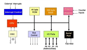
8051 MICROCONTROLLER ARCHITECTURE
Central Processor Unit or CPU:
CPU is the mind of any processing machine. All processes carried out in the Microcontroller are scrutinised and managed by it. The user has no control over the CPU’s operation. It interprets the programme stored in the read-only memory (ROM) and performs all of the tasks assigned to it. In 8051 microcontrollers, the CPU manages various sorts of registers.
Interrupts:
Interrupt, as the name implies, is a subroutine call that reads the Microcontroller’s essential function or task and assists it with performing another programme which is more important at the present time. The 8051 Interrupt feature is incredibly beneficial since it aids in emergency situations. Interrupts allow us to postpone or pause the present process, perform a sub-routine operation, and then restart the regular programme implementation.
The Microcontroller 8051 can be configured in such a way that when an interrupt occurs, it temporarily stops or breaks the core programme. When the sub-routine work is completed, the core programme implementation begins automatically as usual. The 8051 Microcontroller has five interrupt supplies, two of which are peripheral interrupts, two are timer interrupts, and one is a serial port interrupt.
Memory:
The micro-controller needs a program that is a set of commands. This application instructs the Microcontroller on how to complete precise tasks. These programs need a storage space on which they can be accumulated and interpret by the Microcontroller to act upon any specific process.Program memory, often known as code memory, is the memory that is used to accumulate the Microcontroller’s programme. It’s also known as Read-Only Memory (ROM) in layman’s terms.
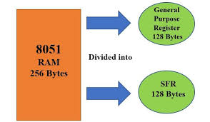
Memory is also required by the microcontroller in order to store data or operands in the short term. The storage area that is used to temporarily store data for functioning is known as Data Memory, and we use Random Access Memory, or RAM, for this purpose. The microcontroller 8051 has a code memory or programme memory of 4K, as well as a 4KB Rom and a 128-byte data memory (RAM).
Bus
Fundamentally, a bus is a set of cables that serve as a communication channel or means of data transport These buses comprise 8, 16, or more cables. As a result, a bus can bear 8 bits, 16 bits altogether. There are two types of buses:
- Address Bus: Microcontroller 8051 comprises of a 16-bit address bus used to address the memory positions. It is also utilized to transmit the address from the Central Processing Unit to Memory.
- Data Bus: Microcontroller 8051 comprises 8 bits data bus. It is employed to cart data.
Oscillator
In-order to perform the timer function in the 8051 microcontroller, an on-chip oscillator is used that function as a time source for the CPU (Central Processing Unit). As we all know, microcontrollers are used in embedded systems to manage device functionalities.
In order to connect it to other machines, gadgets, or peripherals, the microcontroller must have I/O (input/output) interface ports. The Microcontroller 8051 has four input/output ports to connect it to other devices for this purpose.
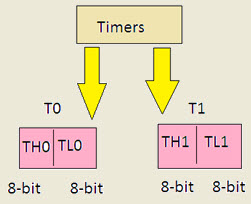
Timers/Counters: The microcontroller 8051 has two 16-bit counters and timers. 8-bit registers are used to separate the counters. Timers are used to measure intervals, determine pulse width, and so on.
Types of Interrupts
The interrupts of the 8051 microcontrollers have the following sources
- TF0 (Timer 0 Overflow Interrupt)
- TF1 (Timer 1 Overflow Interrupt)
- INT0 (External Hardware Interrupt)
- INT1 (External Hardware Interrupt)
- RI/TI (Serial Communication Interrupt)
Memory
The 8051 microcontroller architecture has two memories: a programme memory and a data memory.
- The CPU’s instructions are saved in the Program Memory. It is typically implemented as Read-Only Memory (ROM), which retains the Program stored into it even if the power is turned off or the machine is reset.
- In a microcontroller, data memory is responsible for storing variable values, temporary data, intermediate results, and other data required for the program’s proper operation.
Timer and Control Unit
The fundamental purpose of a timer is to create a delay between two events. This microcontroller has two 16-bit timers, allowing the system to generate two delays at the same time to achieve the desired delay. In general, every microcontroller employs hardware delays, in which a physical device is connected to the CPU and utilised to generate a specific delay, referred to as a timer.
The timer can generate the delay based on the processor’s requirements and communicates the signal to the processor whenever the delay is generated.
A programme counter, data pointer, stack & stack pointer, instruction registers including latches, temporary registers, and buffers for the I/O ports are also included in the microcontroller.
Registers
In microcontrollers, registers are primarily used to store data and short-term instructions, which are mostly utilised to process addresses in order to fetch data. This microcontroller has 8-bit registers with 8-bit start values ranging from D0 to D7. The LSB (least significant bit) ranges from D0 to D7, with D7 being the most significant bit (MSB).
To improve the data processing above 8 bits, it must be divided into eight independent bit pieces. It contains a number of registers, however programmers are more likely to use general-purpose registers. There are two categories of them: general purpose and special purpose. As a result, the majority of the general-purpose registries are mentioned here.
- Accumulator-The fundamental purpose of an accumulator is to perform arithmetic and logic instructions.
- Registers like B, R0 toR7 are used for storing instruction addresses & data.
- Data pointers, also known as DPTRs, are used to allow and process data in various addressing modes. DPH (high byte) and DPL (low byte) make up this register, which is mostly used to store a 16-bit address. As a result, it can be used as a base register for indirect jumps, lookup table instructions, and external data transfers.
- Program counter or PC is a 16-bit register that stores the address of the next instruction to be executed.
- These registers are 8-bits other than program counter & data pointer registers.
Data Types
This microcontroller includes simply one 8 bit data type where the size of each register is 8-bit. If the data is more than 8 bits, the programmer is responsible for separating the data into 8-bit parts before processing. The DB directive in assembly language is the most often used data directive among assemblers.
PSW Register
PSW stands for Program status word, and it is a type of register found in microcontrollers. It’s also known as a flag register, and it’s used to show where arithmetic logic instructions like zero carry bit, carry bit, and so on are located. The flag register, also known as the PSW register, is an 8-bit register with six bits.This register includes 8-flags where these flags are known as conditional flags. These flags will perform instruction simply if the condition is satisfied.
Overflow, parity, auxiliary carry, and carry are the conditional flags. The bit numbers 3 and 4 in the Program status word registers are used to change the bank registers, whereas 1 and 5 are not used but can be used by the programmer to do a specific task.
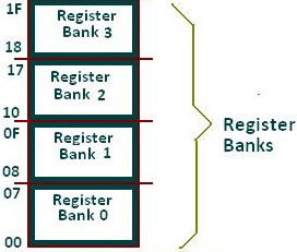
Register Banks
RAM of 32 bytes is used for stacks and register banks, which are divided into four categories. As a result, each bankk has eight registers ranging from R0 to R7. R0 & R7 refer to the zero and seventh RAM locations, respectively. The second bank register starts at 8 and concludes at 05H. The third bank register starts at ten o’clock and ends at seventeen o’clock. The final bank can be found in the 18H-1FH range.
Stack
The Stack section of RAM is mostly used by the processor for data storage, but it is also used for temporary address storing. It plays a crucial role in a microprocessor because the number of registers available for storing addresses and data is quite limited.
The stack in 8051 microcontrollers is 8 bits wide and can hold data from 00 to FFH. The stack pointer can be used to allow the stack through the CPU. Because this microcontroller has an 8-bit stack pointer, it can accept values from 00H to FFH. The stack pointer includes the 07 value once it is triggered.
Organization of Memory
The microcontroller’s memory organisation is complicated, with a separate address bus for programme memory, external RAM, and data memory. It is based on Harvard architecture, which was designed by Harvard in 1944.
Addressing Modes
Microprocessor get data in different methods. Generally, the data stored within memory, register & can be used from instant value. As a result, these various techniques of data access are referred to as addressing modes. Different addressing modes are included in different types of microcontrollers, depending on the manufacturer’s intention. This microcontroller’s addressing modes include the following.
- Register
- Register indirect
- Immediate
- Indexed
- Direct
ADVANTAGES
- Minimum hardware because of the single chip microcomputer system. This reduces the cost.
- Because of less hardware, the PCB size is small.
- It increases system reliability.
- They have smaller access time. Hence, speed of operation is high.
- It is easy to use, troubleshoot and maintain.
- Most of the pins can be programmed by the user in order to perform different functions.
- Micro-controllers have inbuilt serial ports, timer and counters, RAM, ROM, A/D converters, flash memory.
- Micro-controller consume less power.
DISADVANTAGES
- The micro-controllers have a complex architecture than that of a micro-processor. Hence, it is difficult to understand their functionality.
- As micro-controllers are RISC micro-controllers, the length of program is big.
- Only a single WREG/A is present.
- They cannot access the program memory.
- The micro-controller cannot be directly interfaced with high power devices.
APPLICATIONS OF 8051 MICROCONTROLLER
A large number of machines use the microcontroller 8051, mostly because it is simple to incorporate into a project or assemble a machine around it. The following are the important areas 8051

- Consumer Appliances (TV Tuners, Remote controls, Computers, Sewing Machines, etc.)
- Home Applications (TVs, VCR, Video Games, Camcorder, Music Instruments, Home Security Systems, Garage Door Openers, etc.)
- Communication Systems (Mobile Phones, Intercoms, Answering Machines, Paging Devices, etc.)
- Office (Fax Machines, Printers, Copiers, Laser Printers, etc.)
- Automobiles (Air Bags, ABS, Engine Control, Transmission Control, Temperature Control, Keyless Entry, etc)
- Aeronautical and Space
- Medical Equipment
- Defense Systems
- Robotics
- Industrial Process and Flow Control
- Radio and Networking Equipment
- Remote Sensing
CONCLUSION
I hope all of you got an idea of the 8051 microcontroller, as well as,its architecture,advantages, ,and applications.Hope all of you find this article informative. For more queries, contact our online store-MATHA ELECTRONICS