
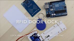
Automatic Access Control System using Arduino and RFID
Unlocking the rooms without using the key in some Hotels and other places has become common nowadays. This Proposed Arduino-based RFID Door Lock mechanism system is a simple and cost-efficient project and can be used as a basic access control mechanism. Here you are provided with a card and you just need to put it in front of an RFID Reader box, and the lock gets unlocked with a Beep and a Blink of LED. This RFID Door Lock can be operated easily at your home and you can install it in any door. This Door lock is just an electrically operating door lock that gets open when you apply some voltage (typically 12v) to it.
Here in this project, we are using Arduino and relay to trigger the Electric Door Lock and RFID to authenticate, so your RFID tag will act as a key. If you place the wrong RFID card near the RFID reader a buzzer will beep to alert you about wrong card. If you are new to RFID first read its working interfacing with Arduino.
This project is a simple design for an RFID door system based on Arduino. As the use, Arduino makes easy design so as by programming code and uploading it to Arduino just like a plug and play device. It. Their main advantage is contactless communication and RFID tags can work in any environmental condition.
How Does RFID System Works?
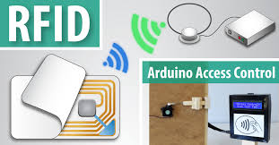
The RFID system comprises of two components: an RFID tag and a Reader. The RFID tag consists of an integrated circuit and an antenna, an integrated circuit designed specifically for the storage of the data, and an antenna is for transmitting the data to the RFID reader module. Whenever the RFID tag comes in the range of RFID reader, RF signal power the tag, and then the tag starts transmitting data serially. The RFID reader further receives data and the reader sends it to the Arduino board. And, after that as per the code in the micro-controller different task performs.
In our system, we have already feed the value of RFID tag in the code. So, whenever that particular tag comes in range, the relay gets activated. Here we have connected a LED with Relay to demonstrate, but an Electric Door Lock can replace this LED, so that whenever the Relay gets activated the lock will be opened.
If we scan any other RFID card, the buzzer will start beeping as it’s the wrong RFID tag. Hence, for the door lock system we have used this concept that the door will only get opened by using the right RFID tag. The relay will itself get deactivated after 5 seconds, the door will be closed after 5 seconds, and you can change this delay in the code.

Components Required:
• Arduino UNO
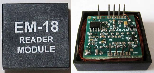
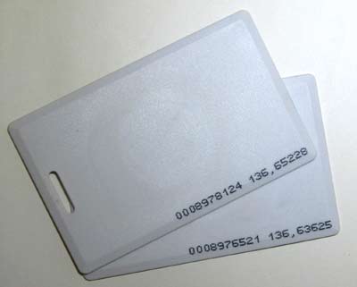
• EM-18 Reader Module with Tags
• Relay 5v
• LED
• Buzzer
• Connecting wire
• Resistors
RFID
Radiofrequency identification is a non-contactless method to transfer data between the transmitter and receiver over a short distance. These modules have application in personal access, toll gate system, control access system, etc. An RFID system consists of a tag attached to the object to be identified with its own unique identification number(UID).only the person with the right information is allowed to enter the door.in this two-way radio transmitter, the reader sends the signal to the tag and reads its response.
.EM-18 RFID reader operates at 125 kHz and it comes with an on-chip antenna and can be powered with a 5V power supply. The output provided by the EM-18 RFID reader is in 12 digit ASCII format. Out of 12 digits, first 10 digits are card numbers and the last two digits are the XOR result of the card number. The last two digits are used for error checking.
ARDUINO UNO
ARDUINO UNO is an integrated, compatible, flexible embedded board based on ATMEGA328. The Arduino Uno has:
• Operating voltage is 5V
• The recommended input Voltage will range from 7v to 12V
• Digital input/output pins are 14
• Analog input pins are 6
• DC Current for each input/output pin is 40 mA
• Flash Memory is 32 KB
• SRAM is 2 KB
• EEPROM is 1 KB
• CLK Speed is 16MHz
Another wonderful feature of the Arduino is the option of using an add-on board to the Arduino which comes as a module and they are known as “Shields”
• Input Voltage: 7-12V
• Number of analog inputs: 6
• Arduino Analog Pin 10
Relay-5v
A relay designed as an electrically operated switch. Many relays operate with an electromagnet to mechanically operate a switch.. Relays functions where it’s necessary to regulate a circuit by a low-power signal. This performed with complete electrical isolation between control and controlled circuits, or several circuits that should be controlled by one signal. This 5V Relay is an automatic control circuit and to control a high-current using a low-current signal. The input voltage of the relay signal ranges from 0 to 5V. This 5V RELAY is controlled directly by Microcontroller Arduino.
Buzzer:
The buzzer is a sounding device that can convert audio signals into sound signals. It is usually powered by DC voltage. In our system, a buzzer beeps out when the wrong RFID card comes in contact with the door system.
REQUIREMENTS
• Computer with an internet connection
• Download and install Arduino IDE
Getting started with Arduino
Arduino Integrated Development Environment (IDE) is a common and prominent software running on the system which allows to write programs in Arduino language for different Arduino boards (sketch). Processing is known as the hardware programming language for Arduino, is somewhat similar to c language. After the sketch is written in the Arduino IDE, it should be uploaded on the Arduino board for execution.
Before starting any project, we need to interface Arduino with computers. So we have to write and compile code for the Arduino to execute, as well as providing Arduino to function with a computer.
Conclusion
In this proposed system, an automatic access control system for use in an environment is designed in a simple and cost effective way. The system uses radio frequency identification (RFID) along with the Arduino technology to differentiate between authorized and unauthorized users using RFID cards and Tags.. The RFID reader reads the RFID tag issued to the user and matches it with the stored UID on the Microcontroller. On a successful match, the microcontroller grants access or denies access if no match was found. If we place the wrong RFID card near the RFID reader a buzzer will beep to alert us about wrong card. An automatic door access control system using Arduino and RFID has been designed and operated as desired. The system can be installed at the entrance of a secured environment to prevent an unauthorized individual access to the environment.