
Blinking LED using GPIO pins of RaspberryPi
The Raspberry Pi is one of the most popular hardware projects in the world. A lot of people have one, but not everyone knows what to do with it. You can use it as a desktop computer or the brain of an electronic circuit.
In this article, we’ll create a basic LED circuit and use the Raspberry Pi Zero W to control it by connecting the circuit to its GPIO pins. So let’s go through the fundamentals of GPIO (general purpose input output) pins and how to get started with physical computing and GPIO using Python.
What are GPIO Pins?
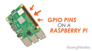
GPIO stands for General Purpose Input/Output. It’s a standard interface for digital input and output used to connect microcontrollers to other electronic devices. For example, it can be used with sensors, diodes, displays, and System-on-Chip modules.
It allows these devices to control external components like rotors and IR transmitters (output) while also receiving data from sensor modules and switches (input) (input). GPIO enables our Raspberry Pi to interface with a wide range of external components, making it suitable for applications ranging from a weather station to a self-driving robot. For GPIO pins to work, software configurations will be required.
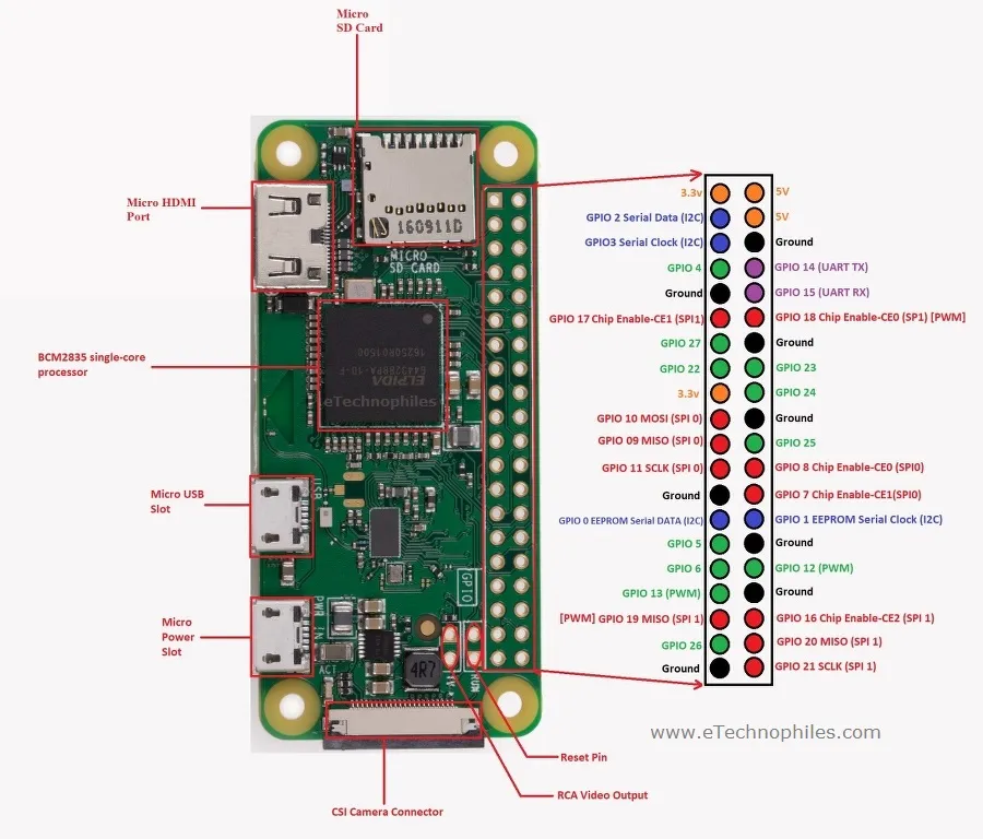
Raspberry Pi Zero GPIO Pinout in detail:
Raspberry PI Zero Power Pins:
The board consists of two 5V pins, two 3V3 pins, and 9 ground pins (0V), which are unconfigurable.
- 5V: The 5v pins deliver the 5v supply from the mains adaptor directly. This pin can be used to power the Raspberry Pi Zero, as well as other 5v devices.
- 3.3V: The 3v pin provides a steady 3.3v supply for powering components and testing LEDs.
- GND: Ground is a term that is often used. All voltages are measured from the GND pin, which also completes an electrical circuit.
Raspberry Pi Zero Input/Outputs pins:
A GPIO pin that is set as an input pin, receives the incoming voltage signal sent by the device connected to this pin. The Raspberry Pi will read a voltage between 1.8V and 3.3V as HIGH, and a voltage less than 1.8V will be read as LOW.
Note: Do not give voltage more than 3.3V to GPIO pins, or else it will fry the Raspberry Pi zero.
When a GPIO pin is set as an output pin, the voltage signal is sent as either high (3.3V) or low (1.5V) (0V). When this pin is set to HIGH, the output voltage is 3.3V, and when it is set to LOW, it is 0V.
Other Important Pins on Raspberry Pi Zero:
In addition to the basic functions of input and output pins, GPIO pins can also perform a range of other tasks. The following are some specific pins:
- PWM (pulse-width modulation) Pins:
- Software PWM available on all pins
- Hardware PWM available on these pins: GPIO12, GPIO13, GPIO18, GPIO19
- SPI PINS on R-Pi Zero:
SPI (Serial Peripheral Interface) is another protocol used for master-slave communication.The Raspberry Pi board uses it to communicate quickly with one or more auxiliary devices. Data is synchronized using a clock (SCLK at GPIO11) from the master (RPi) and the data is sent from the Pi to our SPI device using the MOSI (Master Out Slave In) pin. When an SPI device needs to connect with the Raspberry Pi, it uses the MISO (Master In Slave Out) pin to do so.
- SPI0: GPIO9 (MISO), GPIO10 (MOSI), GPIO11 (SCLK), GPIO8 (CE0), GPIO7 (CE1)
- SPI1: GPIO19 (MISO), GPIO20 (MOSI), GPIO21 (SCLK), GPIO18 (CE0), GPIO17 (CE1), GPIO16 (CE2)
- I2C Pins on R-Pi Zero:
The Raspberry Pi board uses I2C to communicate with devices that are compatible with the Inter-Integrated Circuit standard (a low-speed two-wire serial communication protocol). The master-slave roles between the two devices are required by this communication standard. SDA (Serial Data) and SCL (Serial Control) are the two I2C interfaces (Serial Clock). They work by sending data to and using the SDA connection, with the SCL pin controlling the data transfer speed.
- Data: (GPIO2), Clock (GPIO3)
- EEPROM Data: (GPIO0), EEPROM Clock (GPIO1)
- UART Pins on R-Pi Zero:
Serial communication, often known as UART (Universal Asynchronous Receiver/Transmitter) pins, allows two microcontrollers or computers to interact. The TX pin is used to send serial data, while the RX pin is used to receive serial data from another serial device.
- TX (GPIO14)
- RX (GPIO15)
Blinking LED using GPIO pin –
We’re going to use GPIO pins to flash two LEDs. The easiest connection you can make to the Raspberry Pi zero w’s GPIO (general purpose input output) is to connect to a pin and send a simple digital output voltage. You’ll do this by using the GPIO IO pins to illuminate an LED. To finish the project, you’ll need the following hardware:
Components Required:
- 1 x Raspberry Pi zero W
- 1 x bread board
- 2 x LED light
- 2 x 330 ohm resistor
- 4 x male to female jumper wire
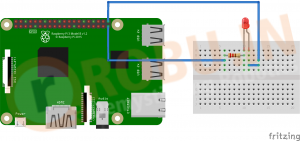
Step 1 – Connections
To make the LED blink, we’ll use GPIO 21 or pin number 40. Ground (0V) at pin 39 will be utilized in series with LED to give ground with a resistance (270,330,1k ohm). Connect the dots using the diagram below –
Step 2 – Writing Python code on Python 3(IDLE)
- Open Python 3 (IDLE) in your Raspberry Pi

- Now Create a new file. And add the code import RPi.GPIO as GPIO # Importing GPIO library
Code
import time LedPin = 40 # Defining pin40 as LedPin def setup(): GPIO.setmode(GPIO.BOARD) # Numbers GPIOs by physical location GPIO.setup(LedPin, GPIO.OUT) # Set LedPin’s mode is output GPIO.output(LedPin, GPIO.HIGH) # Set LedPin high(+3.3V) to turn on led def blink(): while True: GPIO.output(LedPin, GPIO.HIGH) # led on time.sleep(1) # keeping it in previous state for 1 sec GPIO.output(LedPin, GPIO.LOW) # led off time.sleep(1) # keeping it in previous state for 1 sec def destroy(): GPIO.output(LedPin, GPIO.LOW) # led off GPIO.cleanup() # Release resource if __name__ == ‘__main__’: # Program start from here setup() try: blink() except KeyboardInterrupt: # When ‘Ctrl+C’ is pressed, the child program destroy() will be executed. destroy()<code></code> |
Save the code as blink.py
- Now open the terminal and type sudo python blink.py , such command is used to run any python file via terminal
- You can press “Ctrl+C” to stop the program
I hope all of you are clear about how to blink a LED using the GPIO pins of Raspberry Pi.We, MATHA ELECTRONICS, will be back soon with more interesting topics.