
How to Interface LCD with Arduino
Displaying information is one of the crucial steps in electronic projects. So using LCDs has always been one of the most popular ways to display information.
When building an embedded project, you may need to use a serial monitor to ensure that everything is operating properly. However, you do not believe it is time consuming, and you believe it can be halted if the LCD is connected to the Arduino board. Yes, it is doable, so buckle up; in this article, we will learn how to connect a 16 x 2 LCD display to an Arduino board.
16*2 GREEN (LCD DISPLAY MODULE)
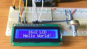
This 1602 LCD module is a very popular display. 16*2 LCD module consists of 16 columns and 2 rows, so it has 32 (16*2) characters in total. Each character has 40pixels (5*8) and thus for 32 characters there 1280 pixels (32*40). An interface IC HD447480 attached to the backside of the LCD module to determine the position of the pixel. This IC gets commands and data from the microcontroller and processes it, thus display it on the screen. The onboard potentiometer used for screen contrast adjustment. It is quite simple to work with these LCDs and they have full compatibility with all microcontrollers and processor boards.

This big character LCD display module comes with black text on a green background. LCD modules are the most prominent as they are low cost and program friendly, hence these modules are commonly used in the embedded system. This display module works on 5V and has a green backlight which can be on or off as per requirement. This module consists of a minimum of 6 I/O pins to interface this LCD screen. Moreover, it can work in both 4 bit and 8-bit MCU interfaces.
PIN DESCRIPTION:

| Pin No | Pin Name | Pin Description |
| Pin 1 | GND | This pin is a ground pin and the LCD is connected to the Ground |
| Pin 2 | VCC | The VCC pin is used to supply the power to the LCD |
| Pin 3 | VEE | Used for adjusting the contrast of the LCD by connecting the variable resistor in between the VCC & Ground. |
| Pin 4 | RS | he LCD consists of two registers, a data register and a command register. These are special-purpose registers.If we make this pin HIGH and put the data on the data line then that data is accepted as the data to be displayed by the LCD. If we make this pin LOW then that data is accepted as a command to the LCD. |
| Pin 5 | R/W | This pin is used to select the operations of Read/Write. To perform the write operations the R/W should be equal to zero. To perform the read operations the R/W should be equal to one. |
| Pin 6 | EN | This is a enable signal pin if the positive pulses are passing through a pin, then the pin function as a read/write pin. |
| Pin 7 | DB0 to DB7 | The pin 7 contains total 8 pins which are used as a Data pin of LCD.Data or commands are given to the LCD display through these pins. |
| Pin 15 | LED + | This pin is connected to VCC and it is used for the pin 16 to set up the glow of backlight of LCD. |
| Pin 16 | LED – | This pin is connected to Ground and it is used for the pin 15 to set up the glow of backlight of the LCD. |
Hardware Required:
- Arduino Board
- LCD Display
Interfacing LCD with Arduino
The following circuit diagram shows the liquid crystal display with the Arduino module. The RS pin of the LCD is connected to pin 12 of the Arduino, as shown in the circuit diagram. The ground is connected to the LCD of the R/W pin. The enable signal pin of the LCD module is connected to pin 11 of the Arduino. This project uses the 4-bit mode to connect the LCD and Arduino modules. As a result, the LCD has four input lines, numbered DB4 to DB7. This process very simple, it requires fewer connection cables and also we can utilize the most potential of the LCD module.

The digital input lines (DB4-DB7) are interfaced with the Arduino pins from 5-2. To adjust the contrast of the display here we are using a 10K potentiometer. The current through the back LED light is from the 560-ohm resistor. The external power jack is provided by the board to the Arduino. Using the PC through the USB port the Arduino can power. Some parts of the circuit can require the +5V power supply it is taken from the 5V source on the Arduino board.
LCD Arduino Code
#include<LiquidCrystal.h> LiquidCrystal lcd(12, 11, 5, 4, 3, 2); // sets the interfacing pins void setup() { lcd.begin(16, 2); // initializes the 16×2 LCD lcd.setCursor(0,0); //sets the cursor at row 0 column 0 lcd.print(“LCD Tutorial”); // prints LCD Tutorial lcd.setCursor(5,1); //sets the cursor at row 1 column 5 lcd.print(“HELLO WORLD”); // prints Robu.in } void loop() { // Your Code } |
We’re utilising the liquid crystal library in this code; it’s a simple to use and comprehend library. I’ve listed a few strategies that will assist you with this endeavour.
| #include LiquidCrystal.h |
This line of code initializes the library and makes the LiquidCrystal library available for the entire code.
| lcd.begin() |
This line of code initiates communication between the LCD and the Arduino. It also tells the Arduino the dimensions of the LCD.
| lcd.print() |
Using the above line of code, you can print letters on the screen.
| lcd.setCursor() |
To move the cursor around on the screen. Where can you put this feature to use? Let’s say you don’t want to start printing characters at the beginning. In that scenario, you can use this procedure to skip the first place and begin printing at the desired location.
Displaying scrolling text on 16×2 LCD with Arduino
#include <LiquidCrystal.h> int speed=0; LiquidCrystal lcd(12, 11, 5, 4, 3, 2); void setup() { lcd.begin(16, 2); //initializes 16×2 LCD lcd.setCursor(0,1) lcd.print(“Tutorial by Robu.in”); //Scrolling Text } void loop() { for(speed=0; speed<2; speed++) { lcd.scrollDisplayRight(); //scrolls display right by two positions } delay(500); //sets the speed at which display moves Please addjust this value if cant see letters clearly. } |
Conclusion
In this blog, we have discussed the basics of LCD modules, how to print characters on an LCD module, and learned how to scroll through text on an LCD.Hope you all find this blog useful See you soon!