
A Basic Introduction to ESP-WROOM-32 Pinout

In this article, we will learn about the ESP32 pinout detail. The ESP32 Pinout will be shown using the 30-pin ESP32 Development Board. We will also learn about various key ESP32 Microcontroller peripherals, their corresponding pins, and which GPIO pins can be used in your project.
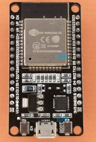
Why do we need to learn ESP32 Pinout?
ESP32-based boards are available in a range of sizes and forms, and each board’s pinout is unique. Additionally, not all of the ESP32 Microcontroller SoC’s pins will be accessible on a development board because some pins might be irreversibly connected to a specific function.
Flash Memory is one example. We are aware that the 4 MB of Flash Memory included on all ESP32 boards is used to store the programs. As a result, six of the GPIO pins are attached to an SPI flash IC and cannot be used as standard GPIO pins.
As a result, it’s critical to comprehend the pinout of typical ESP32 boards so that you can be aware of the pins that are accessible for use in projects.
Introduction to ESP32 Pin Layout
The 48-pin QFN packaging for the ESP32 Microcontroller IC is available. If you want to build your own ESP32 Board, it is challenging to solder the IC onto the PCB because it is a QFN (Quad Flat No Leads) package.

Espressif Systems, the ESP32’s creators, created a compact module board featuring edge castellations using the ESP32 IC. The ESP-WROOM-32 is the name of one popular variation of this module board.
The ESP-WROOM-32 also includes a 4 MB SPI Flash IC, a 40 MHz Crystal Oscillator, a PCB Antenna, and various discrete passive components to create a functional system in addition to the ESP32 IC.

You can use this board to create a development board, a breakout board, or even a for-sale item in your hardware design (as it handles the challenging RF area of the PCB).
Manufacturers of third-party modules perform this. The ESP-WROOM-32 Module is used to create a break-out board with user-friendly pins, a USB port, RESET and BOOT switches, and other features.

ESP-WROOM-32 Pinout
Let’s begin our investigation of the ESP32 Pinout by examining the ESP WROOM 32 Pinout. The pinout of a typical ESP-WROOM-32 module is shown in the next image. It is made of 38-pin (14 pins on each long edge and 10 on the bottom short edge).

The PCB Antenna will use the remaining short edge. If you look at the previous ESP-WROOM-32 image, you will notice that the microcontroller and other components are hidden by the RF shield.
If you’re utilising the ESP-WROOM-32 module in your hardware design, use this pinout as a guide.
ESP32 Pinout
With the exception of a few pins at the bottom, the pinouts of the 30-pin and 36-pin ESP32 Development Boards are nearly identical. Six GPIO pins (GPIO6 to GPIO11) are used for SPI Flash IC in the 36-Pin version. Therefore, they shouldn’t be put to any other uses. Finally, you only receive one more pin (GPIO0 – Pin 23).
Another ESP32 DevKit Board model has 36 pins. The 30-pin variant is more often used than this one. The following pinout, however, will be very useful if you chance to own a 36-pin ESP32 board.

As you can see from the figure, each pin has multiple potential uses. Before using a pin for a certain operation, confirm all of its potential uses.
A different ESP32 DevKit Board model has 36 pins. The 30-pin variant is more often used than this one. The following pinout, however, will be very useful if you chance to own a 36-pin ESP32 board.
With the exception of a few pins at the bottom, the pinouts of the 30-pin and 36-pin ESP32 Development Boards are nearly identical. Six GPIO pins (GPIO6 to GPIO11) are used for SPI Flash IC in the 36-Pin version. Therefore, they shouldn’t be put to any other uses. Finally, you only receive one more pin (GPIO0 – Pin 23).

Important ESP32 Peripherals
After learning a little bit more about the ESP32 Pinout. Let’s now concentrate on a few of the crucial ESP32 peripherals and the pins that go with them. The ESP32 Microcontroller includes:
- 34 Programmable GPIOs
- 18 12-bit ADC Channels
- 2 8-bit DAC Channels
- 16 PWM Channels
- 3 UART Interfaces
- 3 SPI Interfaces
- 2 I2C Interfaces
- 2 I2S Interfaces
- 10 Capacitive Touch Sensing GPIOs
- 16 RTC GPIOs
GPIO
The GPIO is the peripheral that is most frequently used. Each of the 34 GPIO pins on the ESP32 performs multiple tasks (only one will be active). A pin can be set up in the software as a GPIO, an ADC, or a UART.
The manufacturer-specified pins must be used because ADC and DAC pins are predefined. However, every GPIO pin can have various functions such as PWM, SPI, UART, I2C, etc. assigned to it using software.
RTC GPIO
The 16 RTC GPIOs on the ESP32 are a component of the RTC Low-Power subsystem. These pins can be utilized as an external wake-up source to awaken the ESP32 from a deep sleep.
ADC
Two 12-bit SAR Analog to Digital Converter Modules for the ESP32 are available, each with 8 and 10 channels. Therefore, the combined ADC1 and ADC2 blocks contain 18 channels of 12-bit ADC.
The result Digital numbers with 12-bit resolution will fall between 0 and 4093.
DAC
Two separate 8-bit Digital to Analog Converter channels on the ESP32 Microcontroller allow for the conversion of digital values into analog voltage signals. The power supply serves as the input reference voltage for the DAC’s internal resistor network.
DAC functionality is connected to the next two GPIO Pins.
- DAC1 — GPIO25
- DAC2 — GPIO26
Capacitive Touch GPIOs
10 capacitive-sensing GPIOs on the ESP32 SoC may detect changes in capacitance on a pin as a result of touching or getting close to the GPIO Pin with a finger or stylus. Without any additional hardware, these Touch GPIOs can be utilized to construct capacitive touch pads.
SPI
Three SPI blocks (SPI, HSPI, and VSPI) are available on the ESP32 Wi-Fi chip in both master and slave modes. Flash Memory is interfaced with using SPI. Consequently, there are two SPI interfaces.
I2C
Three SPI blocks (SPI, HSPI, and VSPI) are available on the ESP32 Wi-Fi chip in both master and slave modes. Flash Memory is interfaced with using SPI. Consequently, there are two SPI interfaces.
- SDA – GPIO21
- SCL – GPIO22
PWM
16 separate PWM waveform channels with adjustable frequency and duty cycle make up the ESP32 PWM Controller. LEDs and motors can both be driven using the PWM waveform. The duty cycle, channel, and frequency of the PWM signal are all programmable.
What GPIO Pins to use?
The table below lists the GPIO pins along with their input and output capabilities.
| GPIO Pin | Pin on ESP32 | Information |
| 0 | – | Pulled HIGH. Connected to BOOT Button |
| 1 | TX0 | Do not use while TXing |
| 2 | YES | Pulled LOW |
| 3 | RX0 | Do not use while RXing |
| 4 | D4 | Pulled LOW |
| 5 | D5 | Pulled HIGH |
| 6 | – | Connected to SPI Flash IC |
| 7 | – | Connected to SPI Flash IC |
| 8 | – | Connected to SPI Flash IC |
| 9 | – | Connected to SPI Flash IC |
| 10 | – | Connected to SPI Flash IC |
| 11 | – | Connected to SPI Flash IC |
| 12 | D12 | Pulled LOW. Boot fails if pulled HIGH as it sets voltage of internal voltage regulator. |
| 13 | D13 | |
| 14 | D14 | |
| 15 | D15 | Pulled HIGH |
| 16 | RX2 | UART2 RX |
| 17 | TX2 | UART2 TX |
| 18 | D18 | |
| 19 | D19 | |
| 21 | D21 | I2C SDA |
| 22 | D22 | I2C SCL |
| 23 | D23 | |
| 25 | D25 | |
| 26 | D26 | |
| 27 | D27 | |
| 32 | D32 | |
| 33 | D33 | |
| 34 | D34 | Digital Input Only. No Digital Output. |
| 35 | D35 | Digital Input Only. No Digital Output. |
| 36 | YES | Digital Input Only. No Digital Output. |
| 39 | YES | Digital Input Only. No Digital Output. |
GPIOs Connected to SPI Flash IC
Look at the ESP-WROOM-32 Module’s design to see how the SPI Flash Memory IC is connected to GPIOs 6 through 11. Do not utilize these GPIO pins for any other purpose, even if they are available (which they are not on the 30-pin ESP32 Board).
Input only GPIO
There are four GPIO pins that can only be used as a digital input. They are designated as GPIOs 34, 35, 36, and 39.
Interrupts
Interrupts are possible on every GPIO pin.
Boot Strapping Pins
The ESP32 SoC contains five pins for boot strapping. As follows:
- GPIO0 (HIGH during BOOT)
- GPIO2 (LOW during BOOT)
- GPIO5 (HIGH during BOOT)
- GPIO12 (LOW during BOOT)
- GPIO15 (HIGH during BOOT)
These pins are used to put the microcontroller into flashing mode or bootloader mode.
Conclusion
I hope all of you had understood the basics of the ESP-WROOM-32 Module, ESP32 DevKit Development Board, and some important peripherals of EP32. We MATHA ELECTRONICS will be back soon with more informative blogs soon.