
Electric motors are used in almost every industry and in a wide range of applications. Electric motors are available in a wide range of sizes and types. A DC motor, as we all know, is a motor that converts electrical energy into mechanical energy. We can utilize this motor in a variety of applications because of its energy.

The speed control system can be employed in a variety of situations, including managing the movement of robotic vehicles, motors in paper mills, and elevators using various types of DC motors. One of the most useful aspects of a DC motor is its speed control. This blog discusses the Speed control Method of a DC Motor in detail
WHAT IS A DC MOTOR?
In DC Motors, Direct current electric energy is converted into mechanical rotational energy. You can also utilize the device in reverse to generate DC electrical power by turning a motor shaft (making the device function as a generator). The winding connections, in which how the two coils in the motor are coupled to each other, can be used to classify DC motors.

A magnetic field is formed in the stator of a DC motor when it is turned on. The field causes the rotor to rotate by attracting and repelling magnets on the rotor. The commutator, which is hooked to brushes connected to the power source, supplies current to the motor’s wire windings to keep the rotor revolving.

TYPES OF DC MOTORS:
- Permanent Magnet DC Motor (PMDC Motor)
- Separately Excited DC Motor
- Self Excited DC Motor
- Shunt Wound DC Motor
- Series Wound DC Motor
- Compound Wound DC Motor
- Short shunt DC Motor
- Long shunt DC Motor
- Differential Compound DC Motor
Speed Control of DC motor

A DC motor’s speed control is the intentional changing of drive speed. We can manually control the speed of a DC motor or use an automatic control system. This differs from speed regulation, which allows the speed to adjust to a natural variation in speed caused by a change in the load on the shaft.
The Principle of Speed Control
The voltage equation of a simple DC motor is
V = Eb + IaRa
- V is the supplied voltage,
- Eb is the back EMF,
- Ia is the armature current,
- Ra is the armature resistance.
We already know that
Eb = (PøNZ)/60A.
- P – number of poles,
- A – constant
- Z – number of conductors
- N- the speed of the motor
Substituting the value of Eb in the voltage equation, we get
V = ((PøNZ)/60A) + IaRa
Or, V – IaRa = (PøNZ)/60A
i.e., N = (PZ/60A) (V – IaRa)/ ø
The speed of a DC motor (N) is equal to

N = K (V – IaRa)/ ø Where, K is a constant.
The above equation shows that
- Speed of the motor is directly proportional to the supply voltage.
- The Speed of the motor is inversely proportional to armature voltage drop.
- The motor speed is inversely proportional to the flux due to the field findings
Thus, the speed of a DC motor can control in three ways:
- By varying the flux, and by varying the current through the field winding
- By varying the armature voltage, and the armature resistance
- Through the supply voltage
1. Flux Control Method
The magnetic flux varies due to the field winding, allowing the motor’s speed to be varied. Since the magnetic flux is determined by the current passing through the field winding, it may be changed by adjusting the current. This can be accomplished by connecting a variable resistor to the field winding resistor in series.

The rated current flows through the field winding due to a rated supply voltage while the variable resistor is kept at its minimal point, and the speed remains normal. The current via the field winding diminishes as the resistance increases progressively. As a result, the flux produced is reduced. As a result, the motor’s speed exceeds its typical range.
2. Armature Control Method
The voltage drop across the armature is controlled by adjusting the armature resistance. The DC motor’s speed can be controlled using this way. A variable resistor is also used in series with the armature in this manner.
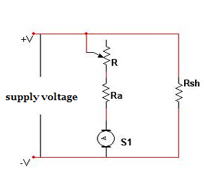
The armature resistance is normal when the variable resistor reaches its minimal value. As a result, the armature voltage falls. The voltage across the armature drops as the resistance value increases. This, in turn, causes the motor’s speed to drop. This approach lowers the motor’s speed below its regular range in this way.
3. Voltage Control Method
Both of the approaches listed above are unable to give speed control in the desired range. Furthermore, the flux control approach can have an impact on commutation. The armature control method, on the other hand, suffers from significant power loss due to the use of a resistor in series with the armature. As a result, a different strategy – controlling the supply voltage to control the motor speed – is frequently preferred.
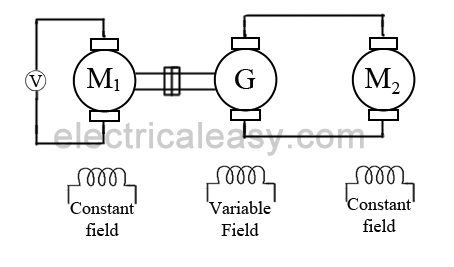
The field winding receives a fixed voltage, but the armature receives a variable voltage in this manner. The use of a switchgear mechanism to supply a changeable voltage to the armature is one such voltage control approach. Another method is to supply variable voltage to the armature using an AC motor-driven generator (named as Ward-Leonard System).
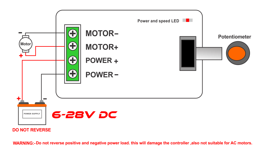
Apart from these two methods, the most generally used method for controlling the speed of a DC motor is pulse width modulation. To adjust the voltage provided to the motor, PWM involves applying varied width pulses to the motor driver. This method is particularly efficient because the power loss is kept to a minimum and no complicated equipment is required.
To adjust the applied voltage of the motor, PWM is performed by altering the pulses applied to the enable pin of the motor driver IC. The microcontroller changes the pulses based on the input signal from the pushbuttons.
Conclusion:
I hope all of you had understand the Speed Control Method of a DC Motor. We will be back soon with more informative blogs.