
How to Design an Arduino Nokia 5110 LCD Menu?

Displaying information is one of the crucial steps in electronic projects. So if you want to display some custom characters or change the font size of the characters or even display some small graphical images, then Nokia 5110 LCD Module is the best option.
In this project, I’ll demonstrate how to create a simple Graphical User Interface system using the Nokia 5110 LCD Display. With the aid of an Arduino board and a few push buttons, I will create a straightforward Nokia 5110 menu interface.
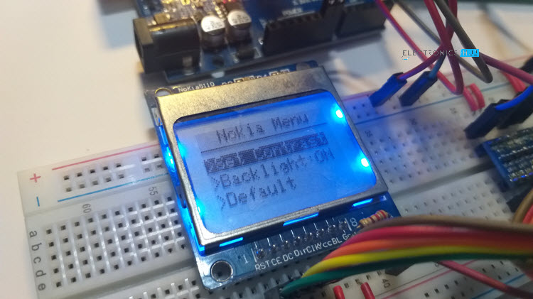
You may develop extremely complicated GUI systems on a variety of Graphical LCD Displays like the Nokia 5110 LCD, 12864 Graphical LCD, etc. by using this Arduino Nokia 5110 LCD Menu Interface as a guide.
What is Nokia 51110 LCD Display Module?

Nokia 51110 LCD Display module developed for use with the iconic Nokia 5110/3316 mobile phone. It is capable of displaying alphanumeric characters, drawing lines, and other shapes, and even displays a bitmap image. All this is possible only because of 84*48 monochrome. Nokia 51110 LCD Display module consists of an inbuilt PCD8544 interface IC which is easy to use with low-level microcontrollers.
The PCD8544 is a low-power CMOS LCD controller. Designed to drive a graphic display of 48 rows and 84 columns. This module communicates through the DSPI protocol, hence there is no need for more pins to communicate. This module has an inbuilt added library for Arduino which makes it ideal for novice programmers.
Nokia 5110 LCD module works on 3.3v and hence all pins are only 3.3 v tolerant. So in case if we are using a 5v microcontroller we need to use a logic level shifter. This level shifter acts like a potential divider to access the SPI pins of the display module. An on-chip generation of the LCD display and a bias voltage are inbuilt in the single-chip LCD display, as a result, minimum, external components and low power consumption is required.

The LCD in the Nokia 5110 comes with a backlight of different colors like green and blue. The bit pattern displays on 50 bytes of Graphic Display Data Ram (GDDR) on the PCD8544 LCD driver. Organized in 6 banks (0 to 5) with each bank containing 84 columns (0 to 83) that store 8 bits of data. Here each bit represents particular pixels on the screen which can programmatically turn ON or OFF.
PCD8544 LCD Controller
Behind the wonderful Nokia 5110 LCD, there lies the PCD8544 LCD Controller from Phillips. It’s a single-chip solution for driving a 48-row, 84-column display. Internally, the PCD8544 Controller has a 504-byte SRAM for storing display data. The SRAM is divided into six banks (Banks 0–5), each of which can store 84 bytes of data. The maximum logic supply voltage is 3.3V. So, proper care must be taken while interfacing with the 5V logic level of Arduino.
NOKIA 51110 LCD DISPLAY MODULE PIN OUT
The pin out of the Nokia 5110 LCD is as follows

- RST: Reset Pin
- SCE: chip select Pin
- D/C: (Data/Command): This is the mode select pin. Low means command mode and high means Data mode.
- DN (Data Pin): Serial Data In
- SCLK: Serial Clock
- VCC: Input voltage is from 2.7 to 3.3V
- LED: This LED is the backlight LED. The input voltage is 3.3V
- GND: Ground
SPECIFICATIONS:
- Display technology: Dot matrix LCD
- MCU interface: SPI
- Screen size: 1.5 inch
- Resolution: 84*48 pixels
- Operating voltage: 2.7v-3.3v
- Operating current: 50mA
- Current consumption: 6mA
- Consist of a Philips PCD8544 interface chip for easy interfacing
- Support decent graphics of bitmap images
- Available in green and blue backlight
- Viewing angle: 180 degree
- supports different types of MCU, such as Arduino, AVR, SPI, M, CS51
- Transfer rate up to 4Mbps, can full speed write data without waiting time
- Dimension:10.16*7.62*1.27cm
- Weight: 10gm
Arduino Nokia 5110 LCD Menu
A screen on display is used to interact with the hardware via a graphic user interface, or simply GUI. Because we receive visual feedback from the hardware, GUI makes it simpler to interact with it.
For instance, you can be creating a straightforward remote monitoring system to determine whether the light is on or off. The task becomes very simple if the system is created so that the status of the light, which may be far away, is shown on a screen close to us.
This Arduino Nokia 5110 Menu Interface tutorial’s objective is to demonstrate how simple it is to create a custom graphical user interface (GUI) system using an Arduino board, a Nokia 5110 LCD, and three push buttons.
On the Nokia 5110 LCD, a “menu” will be shown, and we’ll use the push buttons to browse through it. With this configuration, we can communicate with Arduino via the Nokia 5110 Menu and regulate many settings (like backlight of the LCD and contrast of the display).
Circuit Diagram
The circuit diagram for the Arduino Nokia 5110 LCD Menu Interface System is displayed in the accompanying image.

Components Required
- Arduino UNO
- Nokia 5110 LCD
- Level Converter Module x 2
- Push Buttons x 3
- 220Ω Resistor
- 10 KΩ x 3 (optional, for external pull-up)
- Breadboard
- Breadboard Power Supply
- Connecting Wires
Hardware Connections
The hardware connections resemble the fundamental Arduino and Nokia 5110 LCD interface. However, I have slightly altered the connections to make room for the push buttons and the backlight control (or rather the pins of Arduino, to be precise).
Important Information: The Nokia 5110 LCD can support up to 3.6V of logic voltage. Due to this, I utilised a few logic level converter modules to connect Arduino and the Nokia 5110. Visit the Arduino Nokia 5110 LCD Tutorial for further details on the circuit as well as instructions on how to make it without a logic level converter.
We are aware that the Nokia 5110 LCD uses a serial interface that is similar to SPI. I decided to control the Nokia 5110 LCD using the hardware SPI of the Arduino. The pin connections for the Nokia 5110 LCD Module and Arduino UNO are shown in the following table.
| Nokia 5110 LCD | Arduino UNO |
| RST | Digital IO 8 |
| CE | Digital IO 10 |
| DC | Digital IO 9 |
| DIN | Digital IO 11 |
| CLK | Digital IO 13 |
| VCC | 3.3V |
| BL | Digital IO 7 |
| GND | GND |
As you can see from the table above, I connected the LCD’s BL (backlight) pin to Arduino’s Digital IO pin 7 (via a 220 ohm current limiting resistor) rather than the LCD’s 3.3V (or 5V) pin. This enables us to adjust the display’s backlight as necessary.
Three push buttons are also required in order to implement the “up,” “down,” and “choose” capabilities. The buttons’ other terminals are linked to Digital IO pins 4, 2, and 3 accordingly, with one end of the buttons connected to GND.
A number of push buttons and LEDs are on my IO board. 10K pull-up resistors are used to pull HIGH the push buttons on the board. This indicates that the buttons’ linked Arduino pins are being externally pulled HIGH. I, therefore, don’t need to make any code changes.
You must use the internal pull-up feature in the code if you are not utilizing any external pull-up resistors with the push buttons.
Designing the Nokia 5110 Menu
The Nokia 5110 Menu System has a fairly simple layout. The LCD initially shows the main menu page (let’s call it page 1), which has three menu items and a Title at the top.

“Set Contrast,” “Backlight,” and “Default” are the three menu options, and I’ve given them the moniker “Nokia Menu.” The numbered items on the menu are 1, 2, and 3, accordingly (internally in the code). On a system reset, the first menu item will be highlighted by default (or boot up).
Navigate the Menu
Three push buttons, fittingly titled up, down, and select, allow us to browse the menu. By clicking the up or down buttons, we can highlight (or browse to) other menu items if we are on page 1 and menu item 1 is now highlighted.
The next item will obviously be highlighted if you press the “up” button, and the prior item will be highlighted if you press the “down” button.
The menu items will be circled (or looped) back if you press up or down when you reach the extremes, i.e., either menu item 1 or 3. If menu item 1 is now highlighted, for instance, pressing the up button will highlight menu item 3.
The same holds true if menu item 3 is currently highlighted and you push the down button; menu item 1 will then become highlighted.
Contrast Adjust
Let’s now look at how to set various values. Assume that menu item 1 (Set Contrast) is highlighted and that you are now on page 1. The “Select” button will activate page 2 if you click it. To change the display’s contrast, visit this page.

You can change the contrast on page 2 by pressing the up or down buttons, accordingly. The contrast will be changed when you hit the up or down buttons, or as you move the mouse. The menu item 1 will be highlighted and you can go back to page 1 at any moment by using the “Select” button.
Control the Backlight
Using menu item 2, the Nokia 5110 LCD’s backlight can be turned ON or OFF (Backlight). The backlight is switched ON by default. Highlight menu item 2 on page 1 by using the up or down arrows.

Pressing the “Select” button will turn on and off the backlight once menu item 2 has been highlighted. The current backlight status, which is either ON or OFF, is printed next to menu item 2.
Restore Default Values
The “Default” menu item is the third option. By selecting this option, the display contrast will be reset to “60” and the backlight will be switched ON.

Code
There is no need to repeat the steps if you followed the previous lesson for downloading libraries. But allow me to reiterate my explanation. You need to download a few libraries in order to connect the Nokia 5110 LCD module to Arduino.
Navigate to the Tools -> Manage Libraries… menu in the Arduino IDE. Install the “Adafruit PCD8544 Nokia 5110 LCD Library” by searching for “PCD8544 Nokia.” Use the same search term to install the “Adafruit GFX Library” as well. Both of these libraries must be used in our code.
| #include <SPI.h> | |
| #include <Adafruit_GFX.h> | |
| #include <Adafruit_PCD8544.h> | |
| #define BUTTON_PIN_UP 4 | |
| #define BUTTON_PIN_SELECT 3 | |
| #define BUTTON_PIN_DOWN 2 | |
| #define BACKLIGHT_PIN 7 | |
| // Declare LCD object for SPI | |
| // Adafruit_PCD8544(CLK,DIN,D/C,CE,RST); | |
| Adafruit_PCD8544 display = Adafruit_PCD8544(13, 11, 9, 10, 8); | |
| boolean backLight = true; | |
| int contrastValue = 60; // Default Contrast Value | |
| int displayItem = 1; | |
| int displayPage = 1; | |
| volatile boolean buttonStatusUp = false; | |
| volatile boolean buttonStatusDown = false; | |
| volatile boolean buttonStatusSelect = false; | |
| int readButtonDown = 0; | |
| int readButtonUp = 0; | |
| int readButtonSelect = 0; | |
| int lastButtonStateDown = 0; | |
| int lastButtonStateUp = 0; | |
| int lastButtonStateSelect = 0; | |
| void setup() | |
| { | |
| /*I have pull-up resistors for button on the IO Board*/ | |
| /*If you are connecting only the push buttons without any*/ | |
| /*external pull-up resistors, then use INPUT_PULLUP for internal pull-up*/ | |
| pinMode(BUTTON_PIN_DOWN, INPUT); | |
| pinMode(BUTTON_PIN_UP, INPUT); | |
| pinMode(BUTTON_PIN_SELECT, INPUT); | |
| pinMode(BACKLIGHT_PIN, OUTPUT); | |
| digitalWrite(BACKLIGHT_PIN, HIGH); //Turn Backlight ON | |
| display.begin(); | |
| display.setContrast(contrastValue); //Set contrast to 60 | |
| display.clearDisplay(); | |
| display.display(); | |
| } | |
| void loop() | |
| { | |
| displayMenu(); | |
| readButtonDown = digitalRead(BUTTON_PIN_DOWN); | |
| readButtonUp = digitalRead(BUTTON_PIN_UP); | |
| readButtonSelect = digitalRead(BUTTON_PIN_SELECT); | |
| checkButtonPressDown(); | |
| checkButtonPressUp(); | |
| checkButtonPressSelect(); | |
| if (displayPage == 1 && buttonStatusUp) | |
| { | |
| buttonStatusUp = false; | |
| displayItem–; | |
| if (displayItem == 0) | |
| { | |
| displayItem = 3; | |
| } | |
| } | |
| else if (displayPage == 2 && buttonStatusUp) | |
| { | |
| buttonStatusUp = false; | |
| contrastValue++; | |
| setContrast(); | |
| } | |
| if (displayPage == 1 && buttonStatusDown) | |
| { | |
| buttonStatusDown = false; | |
| displayItem++; | |
| if (displayItem == 4) | |
| { | |
| displayItem = 1; | |
| } | |
| } | |
| else if (displayPage == 2 && buttonStatusDown) | |
| { | |
| buttonStatusDown = false; | |
| contrastValue–; | |
| setContrast(); | |
| } | |
| if (buttonStatusSelect) | |
| { | |
| buttonStatusSelect = false; | |
| if (displayPage == 1 && displayItem == 2) | |
| { | |
| if (backLight) | |
| { | |
| backLight = false; | |
| turnBacklightOff(); | |
| } | |
| else | |
| { | |
| backLight = true; | |
| turnBacklightOn(); | |
| } | |
| } | |
| if(displayPage == 1 && displayItem == 3) | |
| { | |
| DefaultValues(); | |
| } | |
| else if (displayPage == 1 && displayItem == 1) | |
| { | |
| displayPage=2; | |
| } | |
| else if (displayPage == 2) | |
| { | |
| displayPage=1; | |
| } | |
| } | |
| } | |
| void checkButtonPressDown() | |
| { | |
| if (readButtonDown != lastButtonStateDown) | |
| { | |
| if (readButtonDown == 0) | |
| { | |
| buttonStatusDown=true; | |
| } | |
| delay(50); | |
| } | |
| lastButtonStateDown = readButtonDown; | |
| } | |
| void checkButtonPressUp() | |
| { | |
| if (readButtonUp != lastButtonStateUp) | |
| { | |
| if (readButtonUp == 0) | |
| { | |
| buttonStatusUp=true; | |
| } | |
| delay(50); | |
| } | |
| lastButtonStateUp = readButtonUp; | |
| } | |
| void checkButtonPressSelect() | |
| { | |
| if (readButtonSelect != lastButtonStateSelect) | |
| { | |
| if (readButtonSelect == 0) | |
| { | |
| buttonStatusSelect=true; | |
| } | |
| delay(50); | |
| } | |
| lastButtonStateSelect = readButtonSelect; | |
| } | |
| void displayMenu() | |
| { | |
| if (displayPage == 1) | |
| { | |
| display.setTextSize(1); | |
| display.clearDisplay(); | |
| display.setTextColor(BLACK, WHITE); | |
| display.setCursor(13, 0); | |
| display.print(“Nokia Menu”); | |
| display.drawFastHLine(0,10,83,BLACK); | |
| display.setCursor(0, 15); | |
| if (displayItem == 1) | |
| { | |
| display.setTextColor(WHITE, BLACK); | |
| } | |
| else | |
| { | |
| display.setTextColor(BLACK, WHITE); | |
| } | |
| display.print(“>Set Contrast”); | |
| display.setCursor(0, 25); | |
| if (displayItem == 2) | |
| { | |
| display.setTextColor(WHITE, BLACK); | |
| } | |
| else | |
| { | |
| display.setTextColor(BLACK, WHITE); | |
| } | |
| display.print(“>Backlight:”); | |
| if (backLight) | |
| { | |
| display.print(“ON”); | |
| } | |
| else | |
| { | |
| display.print(“OFF”); | |
| } | |
| if (displayItem == 3) | |
| { | |
| display.setTextColor(WHITE, BLACK); | |
| } | |
| else | |
| { | |
| display.setTextColor(BLACK, WHITE); | |
| } | |
| display.setCursor(0, 35); | |
| display.print(“>Default”); | |
| display.display(); | |
| } | |
| else if (displayPage == 2) | |
| { | |
| display.setTextSize(1); | |
| display.clearDisplay(); | |
| display.setTextColor(BLACK, WHITE); | |
| display.setCursor(8, 0); | |
| display.print(“SET CONTRAST”); | |
| display.drawFastHLine(0,10,83,BLACK); | |
| display.setCursor(5, 15); | |
| display.print(“Value”); | |
| display.setTextSize(2); | |
| display.setCursor(5, 25); | |
| display.print(contrastValue); | |
| display.display(); | |
| } | |
| } | |
| void DefaultValues() | |
| { | |
| contrastValue = 60; | |
| setContrast(); | |
| backLight = true; | |
| turnBacklightOn(); | |
| } | |
| void setContrast() | |
| { | |
| display.setContrast(contrastValue); | |
| display.display(); | |
| } | |
| void turnBacklightOn() | |
| { | |
| digitalWrite(BACKLIGHT_PIN, HIGH); | |
| } | |
| void turnBacklightOff() | |
| { | |
| digitalWrite(BACKLIGHT_PIN, LOW); | |
| } |
Conclusion
I hope all of you understand the basics of designing a simple GUI (Graphical User Interface) system with the help of the Arduino based Nokia 5110 Menu Display. We MATHA ELECTRONICS will be back soon with more informative blogs.