
How to Interface ACS712 Current Sensor with Arduino
The discovery of electricity has led in a revolutionary shift in human life. We invented many innovative applications of electricity to make our daily life easier. Almost all of our equipment nowadays is powered by electricity. Current refers to the flow of charge. Depending on their functional requirements, different devices demand different amounts of current.
A sensor is required to measure current in a circuit. The ACS712 Current Sensor can be used to measure and calculate the amount of current applied to the conductor without impacting the system’s performance. We’ll talk about the ACS712 Current Sensor, how a Hall Effect-based current sensor works, and how to connect the ACS712 Current Sensor to an Arduino in this article..
What is the ACS712 Current sensor?
ACS712 Current Sensor is a fully integrated, Hall-effect based linear sensor IC that can measure both DC(Direct Current) and AC(Alternating Current). This current sensor operates at a supply voltage of 5V in which output is proportional to AC or DC current. It has 2.1kVRMS voltage isolation and an integrated low-resistance current conductor
Many industrial, commercial, and communication applications use ACS712. This IC is suitable for use in automobiles. This IC can be found in motor control circuits, load detection and management, SMPS, and overcurrent fault prevention circuits, to name a few.
Specifications:
- 80kHz bandwith
- 66 to 185 mV/A output sensitivity
- Low-noise analog signal path
- Device bandwith is set via the new FILTER pin
- 1.2 mΩ internal conductor resistance
- Total output error of 1.5% at TA = 25°C
- Stable output offset voltage.
- Near zero magnetic hysteresis
PINOUT FOR ACS712 Current sensor
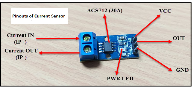
The ACS712 sensor module has 3 pins:
- VCC: Power supply – 5v
- GND: Ground
- OUT: Analog output voltage
Based on the current sensing range, the ACS712 Sensor is divided into three types. +/-5A, +/-20A, and +/-30A are the three ranges.
How does the ACS712 Current sensor work?
Basically, a Current Sensor works on direct sensing or indirect sensing. The direct sensing uses Ohm’s law to measure the voltage drop across the wire when current flows through it. For the ACS712 current sensor, it uses indirect sensing. In order to sense current a liner, low-offset, precise Hall sensor circuit is used in this IC. This sensor was placed at the surface of the IC on a copper conduction path.
When the applied current flows through this copper conduction path it generates a magnetic field sensed by the Hall effect sensor. Hall Sensor generates a voltage proportional to the sensed magnetic field, used to measure current. The present output current signal is read via the analogue I / O port of a microcontroller or an Arduino.
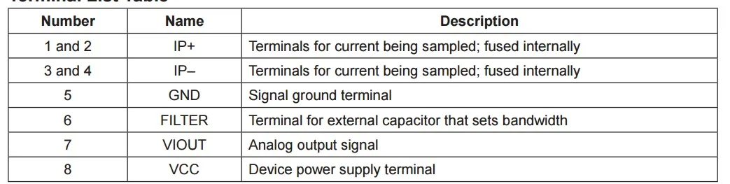
The range of the magnetic signal to the Hall sensor decides the accuracy of the device. Closer the magnetic signal higher the accuracy. ACS712 Current Sensor designed as a compact-sized, surface mount SOIC8 package. In this ACS712 Current Sensor IC, Pin-1 to Pin-4 forms the conduction path where the current is sensed. Pin-5 represents the signal ground pin. Pin-6 indicates the FILTER pin by an external capacitor to set the bandwidth. Pin-7 is the analogue output pin. Pin-8 is the power supply pin.
Components required
- Arduino UNO
- ASC712 Current Sensor Module
- Load (like a lamp or a motor)
- Power supply (for load like battery)
- 16×2 LCD Display
- 10KΩ Potentiometer
- 330Ω Resistor
- Connecting wires
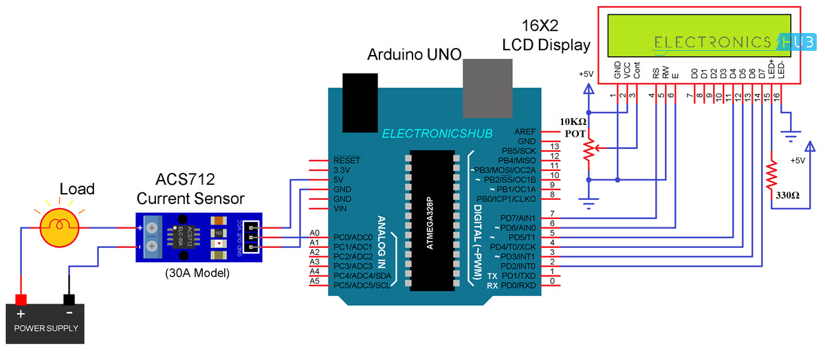
Interfacing ACS712 Current Sensor with Arduino
We’ll need an Arduino or another microcontroller to interface with a current sensor in order to measure the current. The ACS712 current sensor is connected to an Arduino microcontroller as shown in the illustration below. We can measure both AC and DC current using this. As a load, I’m utilising a DC motor.
Software and Programming Code
Download the Arduino IDE Software and the LCD display library for this code from the below links,
- Arduino IDE 1.8.13
- LiquidCrystal Library
#include <LiquidCrystal.h> LiquidCrystal lcd(7, 6, 5, 4, 3, 2); const int currentPin = A0; int sensitivity = 66; int adcValue= 0; int offsetVoltage = 2500; double adcVoltage = 0; double currentValue = 0; void setup() { Serial.begin(9600); lcd.begin(16, 2); lcd.print(” Current Sensor “); lcd.setCursor(0,1); lcd.print(” with Arduino “); delay(2000); } void loop() { adcValue = analogRead(currentPin); adcVoltage = (adcValue / 1024.0) * 5200; currentValue = ((adcVoltage – offsetVoltage) / sensitivity); Serial.print(“Raw Sensor Value = ” ); Serial.print(adcValue); lcd.clear(); delay(1000); //lcd.display(); lcd.setCursor(0,0); lcd.print(“ADC Value = “); lcd.setCursor(12,0); lcd.print(adcValue); delay(2000); Serial.print(“\t Voltage(mV) = “); Serial.print(adcVoltage,3); lcd.setCursor(0,0); lcd.print(“V in mV = “); lcd.setCursor(10,0); lcd.print(adcVoltage,1); delay(2000); Serial.print(“\t Current = “); Serial.println(currentValue,3); lcd.setCursor(0,0); lcd.print(“Current = “); lcd.setCursor(10,0); lcd.print(currentValue,2); lcd.setCursor(14,0); lcd.print(“A”); delay(2500); } |
Applications
The ACS712 sensor can be used in the different types of application and they are,
- Inverters
- SMPS
- Battery Chargers
- Automotive Applications like Inverters
- Peak detection circuits, circuits to increase gain
- Electrical load detection and management
- Used in industrial, commercial and communication applications.
- Rectification application for A/D converters
- Overcurrent fault latch, etc