
The DHT11 is a temperature and humidity sensor that is used to measure the air temperature and humidity in a specific environment or in a confined closed space, as the name implies.
We’ll learn how to connect the popular DHT11 Temperature and Humidity sensor to the STM32 microcontroller in this article. We’ve already covered the fundamentals of the STM32 board and how to use the Arduino IDE with it. In this article, we’ll use an ST Microelectronics STM32F103C8T6 microcontroller to connect to a DHT11 sensor.
Components Required
- STM32F103C8T6 MCU based STM32 Blue Pill Board
- DHT11 Humidity and Temperature Sensor
- 16×2 LCD Display
- PCF8574 I2C LCD Module
- 5KΩ Resistor (Optional, not required if it is present on DHT11 Module)
- Connecting Wires
- USB to UART Converter (needed only if programming through UART)
DHT11 Humidity and Temperature Sensor
The DHT 11 is a low-powered electronic device that lets us get the value of the temperature and the moisture and it uses 1 wire protocol. The sensor consists of a capacitive humidity sensor and a Thermistor connected to a high-performance 8-bit microcontroller. It measures the surrounding air and outputs a digital signal on the data pin (no analogue input pins are needed).DHT11 is strictly factory calibrated that is extremely accurate on humidity calibration, hence easy to interface with other microcontrollers. Using dedicated digital module acquisition technology and temperature, humidity sensors ensures the products with high reliability and excellent long-term stability.

The sensor had a temperature range of 0°C to 50°C with a 1°C precision. It is often used to monitor temperature and perform remedial steps in controlled conditions such as heat ventilation systems, temperature chambers, and so on. Humidity is measured in percentages ranging from 20% to 90%, with a precision of 1%.
Features:
- Operating Voltage: 3.5V to 5.5V
- Operating current: 0.3mA (measuring) 60uA (standby)
- Output: Serial data
- Temperature Range: 0°C to 50°C
- Humidity Range: 20% to 90%
- Resolution: Temperature and Humidity both are 16-bit
- Accuracy: ±1°C and ±1%
Pinout for DHT11 Humidity and Temperature Sensor

- VCC: This pin is used to supply power to the sensor. Although supply voltage ranges from 3.3V to 5.5V, a 5V supply is recommended. With a 5V power supply, the sensor can be kept for up to 20 metres. With a 3.3V supply voltage, however, the cable length must not exceed 1 metre. Otherwise, the line voltage drop will cause measurement mistakes.
- Data: Used to communicate between the sensor and the microcontroller.
- NC: Not connected
- GND: Should be connected to the ground of Arduino.
STM32F103C8T6 DISCOVERY BOARD
STM32F103C8T6 Discovery Board was designed as a development board that is similar to Arduino in terms of advanced capabilities and accessibility. The STM32Discovery Board enables the development of high-reliability applications by utilizing an advanced performance microcontroller known as the Arm Cortex-M4 32-bit core. I think you’re familiar with ARM Architecture. It provides versatility and customization, allowing you to experiment with libraries, communication protocols, GPIO pins, and so on.

Interfacing DHT11 Humidity and Temperature Sensor with STM32F103C8T6
Before proceeding further, I’d like to remind you of something from the DHT11 Sensor’s datasheet. The sole data line between the DHT11 Sensor and the Microcontroller, in this case, the STM32, must be pulled HIGH with the help of a 5K Resistor, according to the datasheet.

So, if you’re looking for a DHT11 Sensor, look for a module that includes the mentioned pull-up resistor (and even some power-on LED). This eliminates the requirement for any additional components when interfacing the DHT11 Humidity and Temperature Sensor with the STM32F103C8T6.
Circuit Diagram
The circuit diagram for interfacing DHT11 Humidity and Temperature Sensor with STM32F103C8T6 MCU based STM32 Blue Pill board is shown in the image below.
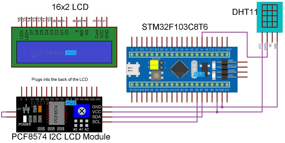
Connections Explained
First, connect the VCC and GND pins of the DHT11 Sensor to +5V and GND respectively. Then connect the sensor’s Data pin to the STM32 board’s pin PA1.
Connect the SDA and SCL pins of the PCF8574 Module to the PB7 and PB6 pins of the STM32 board, respectively, and plug the PCF8574 I2C LCD Module into the back of the LCD. Connect the I2C LCD Module’s VCC and GND pins to +5V and GND, respectively.
Programming STM32 for Interfacing DHT11
Before proceeding, make sure you’ve figured out the PCF8574 Module’s slave address as described in the I2C LCD Tutorial. You can use the following code for the same.
| #include <Wire.h> void setup() { Wire.begin(); Serial.begin(9600); while (!Serial); } void loop() { byte error, address; int I2CDevices; Serial.println(“Scanning for I2C Devices…”); I2CDevices = 0; for (address = 1; address < 127; address++ ) { Wire.beginTransmission(address); error = Wire.endTransmission(); if (error == 0) { Serial.print(“I2C device found at address 0x”); if (address < 16) Serial.print(“0″); Serial.print(address, HEX); Serial.println(” !”); I2CDevices++; } else if (error == 4) { Serial.print(“Unknown error at address 0x”); if (address < 16) Serial.print(“0”); Serial.println(address, HEX); } } if (I2CDevices == 0) Serial.println(“No I2C devices found\n”); else Serial.println(“****\n”); delay(5000); } |
Now, coming to the actual program, first, download the DHT library from this link. Extract the zip file and copy the contents to the libraries folder of your local Arduino installation. This path will be usually “C:\Program Files (x86)\Arduino\libraries”.
Then, in the programme, specify PA1 as the DHT Data Pin and DHT11 or DHT22 as the DHT Sensor Type. Using the LiquidCrystal_I2C library function, declare the I2C LCD by specifying the slave address, number of columns, and rows. You may now use the “begin” routines to initialise both the LCD and the DHT11 Sensor.
Now, take two float values and grab the Humidity and Temperature readings from the sensor using two float values. Print these values on the LCD at the end.
Code
| #include <Wire.h> #include <LiquidCrystal_I2C.h> #include <DHT.h> #define DHTPIN PA1 #define DHTTYPE DHT11 LiquidCrystal_I2C lcd(0x27, 16, 2); DHT dht(DHTPIN, DHTTYPE); byte degree_symbol[8] = { 0b00111, 0b00101, 0b00111, 0b00000, 0b00000, 0b00000, 0b00000, 0b00000 }; void setup() { lcd.begin(); dht.begin(); lcd.backlight(); lcd.setCursor(0,0); lcd.print(“Electronics Hub”); lcd.setCursor(0,1); lcd.print(“DHT11 with STM32”); delay(2000); lcd.clear(); lcd.setCursor(0,0); lcd.print(“Temp = “); lcd.setCursor(0,1); lcd.print(“Humid = “); lcd.createChar(0, degree_symbol); lcd.setCursor(12,0); lcd.write(0); lcd.print(“C”); lcd.setCursor(14,1); lcd.print(“%”); } void loop() { float hum = dht.readHumidity(); float tem = dht.readTemperature(); lcd.setCursor(7,0); lcd.print(tem); lcd.setCursor(8,1); lcd.print(hum); } |
Conclusion
Hope this blog helps you to understand the Interfacing of DHT11 Humidity and Temperature Sensor with STM32F103C8T6 MCU based STM32 Blue Pill Board. We, MATHA ELECTRONICS will come back with more informative blogs.