
How to Interface Rotary Encoder with Arduino?
A Rotary encoder is a type of position sensor that converts the angular position (rotation) of a knob into an output signal that is used to determine what direction the knob is being rotated. They are employed in a variety of applications, including robotics, CNC machines, and printers, due to their robustness and fine digital control.

In this blog we are going to discuss about the basics of Rotary Encoder, and how to interface it with Arduino in detail.Lets Get Started
What Is a Rotary Encoder?
Rotary encoders are sensors that convert rotational mechanical displacements into electrical signals and process them to detect location and speed. Rotary Encoders measure the number of rotations, the rotational angle, and the rotational position.
The Angular position or motion of a shaft or axle is converted to analogue or digital output signals by a rotary encoder, also known as a Shaft encoder. Absolute and Incremental rotary encoders are the two most common varieties. An Absolute encoder is an angle transducer since its output indicates the current shaft position. An Incremental encoder’s output offers information on the shaft’s motion, which is often processed into information like position, speed, and distance.

Features
- The output is controlled based on the shaft’s rotational displacement.
Linking to the shaft using a coupling enables direct detection of rotational displacement.
- Returning to the origin is not required at startup for Absolute Encoders.
With an Absolute Encoder, the rotational angle is output in parallel as an Absolute value. (Refer to Operating Principles of below.)
- The direction of rotation can be determined.
With an Incremental Encoder, the rotation direction is defined by the output timing of phases A and B, while with an Absolute Encoder, the code increase or decrease. (For more information, see the Operating Principles section below.)
- From a variety of resolutions and output kinds, select the best Sensor. Choose the Sensor that best fits your needs.
Rotary Encoder Pinout
The pinouts of the rotary encoder are as follows:

- GND connection is used to connect to the ground.
- VCC is the positive supply voltage, commonly 3.3 or 5 volts
- SW is the output of an active low push button switch. The voltage goes LOW when the knob is pressed.
- DT (Output B) output is identical to the CLK output, however it is 90 degrees behind the CLK. The direction of rotation can be determined using this output.
- CLK (Output A) is the primary output pulse for determining the amount of rotation. Each time the knob is rotated by one detent (click) in either direction, the ‘CLK’ output goes through one cycle of going HIGH and then LOW.
How Rotary Encoder Works?
Let’s look at the encoder in more detail and see how it works. The square wave pulses are generated as follows: As seen below, the encoder has a disc with equally spaced contact zones that are connected to the common pin C as well as two distinct contact pins A and B.

When the disc begins to rotate in steps, pins A and B will make contact with the common pin, resulting in the generation of two square wave output signals.
If we just count the pulses of the signal, we can determine the rotational position using any of the two outputs. However, we must analyse both signals at the same time if we wish to determine the rotation direction.
It is clear that the two output signals are 90 degrees out of phase with one another. The output A will be ahead of the output B if the encoder rotates clockwise.

Counting the steps each time the signal changes, from High to Low or Low to High, we can see that the two output signals have opposite values at that time. In the opposite case, when the encoder rotates counterclockwise, the output signals have the same value. As a result, we can easily configure our controller to read the encoder location and rotation direction using this information.
Interfacing Rotary Encoder with Arduino
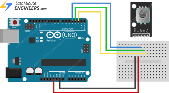
Let’s connect Rotary Encoder to Arduino. Connections are fairly simple. Start by connecting +V pin on the module to 5V on the Arduino and GND pin to ground.
Now connect the CLK and DT pins to digital pin#2 and #3 respectively. Finally, connect the SW pin to a digital pin #4.
Program Code
| // Rotary Encoder Inputs #define CLK 2 #define DT 3 #define SW 4 int counter = 0; int currentStateCLK; int lastStateCLK; String currentDir =””; unsigned long lastButtonPress = 0; void setup() { // Set encoder pins as inputs pinMode(CLK,INPUT); pinMode(DT,INPUT); pinMode(SW, INPUT_PULLUP); // Setup Serial Monitor Serial.begin(9600); // Read the initial state of CLK lastStateCLK = digitalRead(CLK); } void loop() { // Read the current state of CLK currentStateCLK = digitalRead(CLK); // If last and current state of CLK are different, then pulse occurred // React to only 1 state change to avoid double count if (currentStateCLK != lastStateCLK && currentStateCLK == 1){ // If the DT state is different than the CLK state then // the encoder is rotating CCW so decrement if (digitalRead(DT) != currentStateCLK) { counter –; currentDir =”CCW”; } else { // Encoder is rotating CW so increment counter ++; currentDir =”CW”; } Serial.print(“Direction: “); Serial.print(currentDir); Serial.print(” | Counter: “); Serial.println(counter); } // Remember last CLK state lastStateCLK = currentStateCLK; // Read the button state int btnState = digitalRead(SW); //If we detect LOW signal, button is pressed if (btnState == LOW) { //if 50ms have passed since last LOW pulse, it means that the //button has been pressed, released and pressed again if (millis() – lastButtonPress > 50) { Serial.println(“Button pressed!”); } // Remember last button press event lastButtonPress = millis(); } // Put in a slight delay to help debounce the reading delay(1); } |
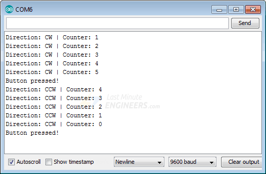
If everything is fine, you should see the below output on the serial monitor.
Output:
Code Explanation:
The sketch begins with the declaration of the Arduino pins to which the encoder’s CLK, DT, and SW pins are connected.
| #define CLK 2 #define DT 3 #define SW 4 |
The next step is to specify a few integers. The counter variable represents the number of times the count is changed when the knob is spun one detent (click).
The currentStateCLK and lastStateCLK variables are used to determine the amount of rotation by storing the state of the CLK output.
When printing the current direction of rotation on the serial monitor, a string called currentDir will be utilized.
The variable lastButtonPress is used to debounce a switch.
| int counter = 0; int currentStateCLK; int lastStateCLK; String currentDir =””; unsigned long lastButtonPress = 0; |
The connections to the encoder are now defined as inputs in the Setup section, and the input pull-up resistor on the SW pin is enabled. The serial monitor was also set up.
Finally, we read the current CLK pin value and save it in the lastStateCLK variable.
| pinMode(CLK,INPUT); pinMode(DT,INPUT); pinMode(SW, INPUT_PULLUP); Serial.begin(9600); lastStateCLK = digitalRead(CLK); |
We check the CLK state again in the loop section and compare it to the lastStateCLK value. If they’re not the same, it’s because the knob has been turned and a pulse has happened. To avoid double-counting, we also check if the value of currentStateCLK is 1. This allows us to react to only one state change.
| currentStateCLK = digitalRead(CLK); if (currentStateCLK != lastStateCLK && currentStateCLK == 1){ |
The direction of rotation is determined within the if statement. To do so, we simply read the encoder module’s DT pin and compare it to the CLK pin’s present state.
If they’re not the same, the knob has been turned counterclockwise. The counter is then decremented, and currentDir is set to “CCW.”
If the two numbers are the same, the knob has been rotated clockwise. The counter is then incremented, and currentDir is set to “CW.”
| if (digitalRead(DT) != currentStateCLK) { counter –; currentDir =”CCW”; } else { counter ++; currentDir =”CW”; } |
We then print our results on the serial monitor.
| Serial.print(“Direction: “); Serial.print(currentDir); Serial.print(” | Counter: “); Serial.println(counter); |
Outside the if statement we update lastStateCLK with the current state of CLK.
| lastStateCLK = currentStateCLK; |
The logic to read and debounce the push button switch comes next. If the current button state is LOW, we wait 50 milliseconds to debounce the push button.
If the button remains LOW for more than 50 milliseconds, the serial monitor displays the message “Button pressed!”
int btnState = digitalRead(SW); if (btnState == LOW) { if (millis() – lastButtonPress > 50) { Serial.println(“Button pressed!”); } lastButtonPress = millis(); } |
Arduino Code – Using Interrupts
We must constantly monitor changes in the DT and CLK signals in order for the rotary encoder to perform.
We can poll them on a regular basis to see when such changes occur (like we did in our previous sketch). However, for the reasons listed below, this is not the best option.
- We must execute rapid checks to detect if a value has changed. If the signal level does not change, there will be a waste of cycles.
- There will be latency from the time the event happens to the time when we check. If we need to react immediately, we will be delayed by this latency
- If the period of a signal shift is short, it is possible to entirely miss it.
The use of an interrupt is a widely used solution.
You don’t have to query the specific event as often with interrupts. This allows the Arduino to focus on other tasks while still ensuring that the event is not missed.
ConclusionHope this blog helps you to understand the basics of Rotary Encoder, and how to interface it with the Arduino. We, MATHA ELECTRONICS will come back with more informative blogs.