
How to Interface Sim800L with Arduino?

If you’re an Electronics enthusiast, you might be interested in experimenting with cell phone connections. I’ve seen several projects that are activated by SMS or voice instructions, but the majority of them use ancient phones. So here we are seeking the help of the SIM800L GPRS Module for this Purpose. In this blog, we will be discussing the basics of the SIM800L GPRS Module and how to interface it with Arduino in detail.
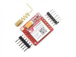
SIM800L GSM/GPRS module designed as a miniature GSM modem can be integrated into a great number of IoT projects. This SIM800L GSM/GPRS module performs a similar function as a normal cell phone can. It can SMS text messages, make or receive phone calls, connect to the internet through GPRS, TCP/IP, and more. Moreover, the module supports quad-band GSM/GPRS network, which indicates that it works pretty much anywhere in the world.
SIM800L GSM/GPRS module-In Detail
SIM800L GSM cellular chip from SimCom is the heart of this module. It supports the UART protocol to communicate with the microcontroller at a baud rate range from 1200bps to 115200bps with Auto-Baud detection. All the necessary data pins of the SIM800L GSM chip are broken out to 0.1″ pitch headers. The module chip operates at a voltage range from 3.4V to 4.4V, making it an ideal solution for direct LiPo battery supply. This makes wide usage for embedding into projects without a lot of space.
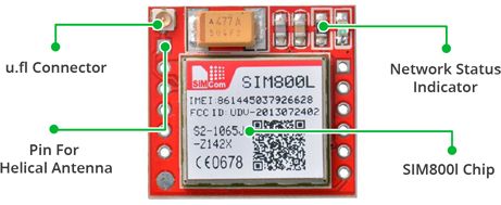
An external antenna is used for any kind of voice or data communications as well as some SIM commands. This module usually comes with a Helical Antenna soldered directly to the NET pin on PCB. Else a 3dBi GSM antenna along with a U.FL to SMA adapter is highly recommended for better performance. It also consists of an onboard U.FL connector facility to keep the antenna away from the board when necessary.A SIM socket on the back of the module helps the 2G micro SIM card work perfectly. Inserting sim incorrect direction normally engraved on the surface of the SIM socket.
.
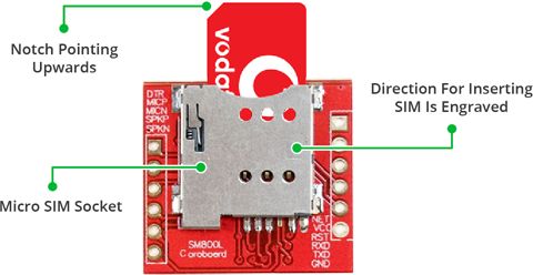
A SIM socket on the back of the module helps the 2G micro SIM card work perfectly. Inserting sim incorrect direction normally engraved on the surface of the SIM socket. The onboard LED indicates the working status, When blinked for every 1s Indicates the module is running but no connections are made to any cellular network. Whereas blinking for every 2s resembles the requested GPRS data connection is active. Finally, blinking every 3s means the module has made contact with the cellular network & can send/receive voice and SMS.
Features
- Chip: SIM800L
- Supports Quad-band: GSM850, EGSM900, DCS1800, and PCS1900
- Operating voltage: 3.7V -4.2V
- Current: 2A
- Quad-band (850/900/1800/1900MHz) supports
- Connect onto any global GSM network with any 2G SIM
- Make and receive voice calls using an external 8Ω speaker & electret microphone
- Send and receive SMS messages
- Send and receive GPRS data (TCP/IP, HTTP, etc.)
- Scan and receive FM radio broadcasts
- Transmit Power:
- Class 4 (2W) for GSM850
- Class 1 (1W) for DCS1800
- Serial-based AT Command Set
- FL connectors for cell antennae
- Searches for network and login automatically
- AT command interface with auto baud detection
- Lead-out buzzer and vibration motor control port
- Interface: UART (max 2.8V, serial interface)
- Command support: 3G PP TS 27. 007, 27. 005 and SIMCOM enhanced AT commands
- Sim Card Slot: Micro SIM
- Temperature range: -40℃ to 85℃
Connecting SIM800L GSM module to Arduino UNO
Hardware Parts
- Arduino Uno
- SIM800l module
- Connecting cables
- 2G Sim card (Please note SIM800l is a 2g GSM module, this means that the 4G sim card will not work with this module. If you are looking for 4G GSM module then click on this link)
Note- If you are using an Arduino as a microcontroller and not using a resistor divider Ckt then you will damage the Sim800l module.
Softwares Required
SIM800L Interfacing with Arduino Uno
Now we know everything about the module,lets start interfacing it with the Arduino
To begin, solder or connect the antenna, then insert a fully active Micro SIM card into the socket. As we’ll be utilizing software serial to communicate with the module, connect the Tx pin on the module to digital pin#3 on the Arduino.
Since the Arduino Uno utilizes 5V GPIO, we can’t connect the Rx pin on the module to the Arduino’s digital pin because the SIM800L module employs 3.3V level logic and it’s not 5V tolerant. This means that the Arduino Uno’s Tx signal must be brought down to 3.3V to avoid damaging the SIM800L module. There are a few options, but the simplest is to use a simple resistor divider. A 10K resistor between the SIM800L Rx and the Arduino D2 would suffice, as would a 20K resistor between the SIM800L Rx and GND.
Now we’re only dealing with the pins that supply power to the module. We’ve supplied two example schematics because there are several ways to power up the module. One employs a Li-Po battery with a capacity of 1200mAh, while the other makes use of an LM2596 DC-DC buck converter.

You’re now ready to play with Sim800l. When you power this module after connecting, you’ll see that the onboard LED is on and blinking in different patterns. The operating state of the SIM800l module is shown by the blinking pattern of the onboard LED.When blinked for every 1s Indicates the module is running but no connections are made to any cellular network.

Whereas blinking for every 2s resembles the requested GPRS data connection is active.

Finally, blinking every 3s means module has made contact with the cellular network & can send/receive voice and SMS.

Troubleshooting SIM800L Module
We learnt about the blinking pattern of the onboard LED and we can determine whether the module is functional or not by evaluating this factor, but this is insufficient if the problem is in the UART port. We can use AT commands to test the port and SIM’s functionality, and we can use the following troubleshooting AT instructions to do so.
Using At Commands to Test the SIM800L Module
To test the module, use Arduino to connect the SIM800l module to your system
- Open Arduino IDE and choose the com port
- Activate the serial monitor
- Enter the AT commands listed below:
- AT: If the Sim800l module is working properly, Sim800l will respond OK when this module is received.
- The AT+CBC command is used to check the voltage of the battery. After receiving this AT command, the Sim800l module reports the signal strength.
- AT+CREG- If your SIM800l module loses network and takes a long time to scan the network, you can use this AT command to register the network.
- SIM800l will tell you about its network status if you use the AT+COPS? command.
- AT+COPS=? -Sim800l tells us the networks available after receiving this AT command.

Setting the Baud Rate
The SIM800L’s default baud rate is 9600, but you can change it with the AT command to any baud rate you want.
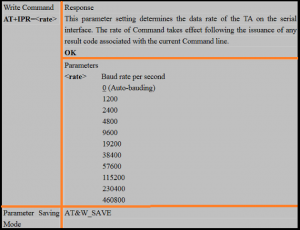 Baud Rate Setting[/caption] |
 Baud Rate AT Commands[/caption] |
Scanning Network
By default, the module scans the network automatically; however, if it does not, you can manually scan the network with the AT command below.

Dialing a Number using SIM800L
Making a Call Using Serial Monitor
 AT Command Set For Dialing The Number[/caption] |
 Calling Screen-Shot[/caption] |

Arduino Sample Code For Sim800L
I’ve included some sample SIM800L codes in the section below; by using these codes, you’ll be able to send and receive SMS.
Troubleshooting Guide
If you use the following code, then your module should work, but it is not working then there may be the following reasons:
- Out of Coverage Area:
You can use the AT + COPS command to see if it’s connected to the network in this case. There could be another problem, which is a power issue. To ensure that you can complete AT + CSQ and AT + CBC. AT + CSQ displays the signal strength, whereas AT + CBC displays the battery %.
- Functionality is Enabled
If all the above works are working and you have followed this blog from the beginning and still it is not sending SMS then the issue may be here. To solve this problem, type AT + CFUN = 1 on the command prompt. This command turns on the module’s functionality.
Sample Code For Dialing a Number:
#include <SoftwareSerial.h> String inputString = “”; String fromGSM = “”; SoftwareSerial mySerial(3, 2); char sim800l[255]; int sim800lIndex = 0; void setup() { // put your setup code here, to run once: Serial.begin(9600); mySerial.begin(9600); inputString.reserve(200); fromGSM.reserve(200); Serial.println(” Command –> AT “); mySerial.print(“AT”); mySerial.print(“\r”); delay(100); Serial.print(” Response –> “); while (mySerial.available()) { sim800l[sim800lIndex] = mySerial.read(); sim800lIndex++; Serial.print( sim800l[sim800lIndex – 1]); } sim800lIndex = 0; Serial.println(“”); Serial.println(” Command –> ATEO “); Serial.print(” Response –> “); mySerial.print(“ATE0”); mySerial.print(“\r”); delay(100); while (mySerial.available()) { sim800l[sim800lIndex] = mySerial.read(); sim800lIndex++; Serial.print( sim800l[sim800lIndex – 1]); } sim800lIndex = 0; Serial.println(“”); Serial.println(” Command –> AT+CFUN=1 “); Serial.print(” Response –> “); mySerial.print(“AT+CFUN =1”); mySerial.print(“\r”); delay(100); while (mySerial.available()) { sim800l[sim800lIndex] = mySerial.read(); sim800lIndex++; Serial.print( sim800l[sim800lIndex – 1]); } sim800lIndex = 0; Serial.println(“”); mySerial.print(“ATD8888844444;”); // enter number ATD<number> mySerial.print(“\r”); while ( !(mySerial.available()) ); while (mySerial.available()) { sim800l[sim800lIndex] = mySerial.read(); sim800lIndex++; Serial.print( sim800l[sim800lIndex – 1]); } sim800lIndex = 0; Serial.println(” “); Serial.println(” Enter ‘ATH’ command to End the call “); } void loop() { while (1) { while (Serial.available()) { sim800l[sim800lIndex] = Serial.read(); sim800lIndex++; mySerial.print( sim800l[sim800lIndex – 1]); } while (mySerial.available()) { sim800l[sim800lIndex] = mySerial.read(); sim800lIndex++; if (sim800l[sim800lIndex – 4] == ‘R’ && sim800l[sim800lIndex – 3] == ‘I’ && sim800l[sim800lIndex – 2] == ‘N’ && sim800l[sim800lIndex – 1] == ‘G’) { delay(8000); mySerial.print(“ATA”); // AT command to answer the call. mySerial.print(“\r”); } Serial.print( sim800l[sim800lIndex – 1]); } } } |
Reading SMS Automatically:
#include <SoftwareSerial.h> String inputString = “”; String fromGSM = “”; SoftwareSerial mySerial(3, 2); char Sim800L[255], SMS[255], smsMemory[5], SmS_Index[5]; int Sim800LIndex = 0, SMS_Index = 0, S_Index = 0; bool NewSMSArrived = 0, SMSmemory = 0; void setup() { Serial.begin(9600); mySerial.begin(9600); inputString.reserve(200); fromGSM.reserve(200); Serial.println(” Command –> AT “); mySerial.print(“AT”); mySerial.print(“\r”); delay(100); Serial.print(” Response –> “); while (mySerial.available()) { Sim800L[Sim800LIndex] = mySerial.read(); Sim800LIndex++; Serial.print( Sim800L[Sim800LIndex – 1]); } Sim800LIndex = 0; Serial.println(“”); Serial.println(” Command –> ATEO “); Serial.print(” Response –> “); mySerial.print(“ATE0”); mySerial.print(“\r”); delay(100); while (mySerial.available()) { Sim800L[Sim800LIndex] = mySerial.read(); Sim800LIndex++; Serial.print( Sim800L[Sim800LIndex – 1]); } Sim800LIndex = 0; Serial.println(“”); Serial.println(” Command –> AT+CFUN=1 “); Serial.print(” Response –> “); mySerial.print(“AT+CFUN =1”); mySerial.print(“\r”); delay(100); // while( ! (mySerial.available()) ); while (mySerial.available()) { Sim800L[Sim800LIndex] = mySerial.read(); Sim800LIndex++; Serial.print( Sim800L[Sim800LIndex – 1]); } Sim800LIndex = 0; Serial.println(“”); Serial.println(” Command –> AT+CMGF=1 “); Serial.print(” Response –> “); mySerial.print(“AT+CMGF =1”); mySerial.print(“\r”); delay(100); // while( ! (mySerial.available()) ); while (mySerial.available()) { Sim800L[Sim800LIndex] = mySerial.read(); Sim800LIndex++; Serial.print( Sim800L[Sim800LIndex – 1]); } Serial.println(” Command –> AT+CSCS=\”GSM\””); Serial.print(” Response –> “); mySerial.print(“AT+CSCS =\”GSM\””); mySerial.print(“\r”); delay(100); // while( ! (mySerial.available()) ); while (mySerial.available()) { Sim800L[Sim800LIndex] = mySerial.read(); Sim800LIndex++; Serial.print( Sim800L[Sim800LIndex – 1]); } Serial.println(” Command –> AT+CPMS=\”SM\””); Serial.print(” Response –> “); mySerial.print(“AT+CPMS =\”SM\””); mySerial.print(“\r”); delay(100); // while( ! (mySerial.available()) ); while (mySerial.available()) { Sim800L[Sim800LIndex] = mySerial.read(); Sim800LIndex++; Serial.print( Sim800L[Sim800LIndex – 1]); } /* Serial.println(” Command –> AT+CMGS=\”8669026867\””); Serial.print(” Response –> “); mySerial.print(“AT+CMGS=\”8669026867\””); mySerial.print(“\n”); delay(100); //while( ! (mySerial.available()) ); while(mySerial.available()) { Sim800L[Sim800LIndex] = mySerial.read(); Sim800LIndex++; Serial.print( Sim800L[Sim800LIndex-1]); } mySerial.print(” ENTER THE TXT YOU WISH TO SEND IN THE SMS “); mySerial.write(0x1A); */ Serial.print(” CHECK THE DESTINATION DEVICE “); } void loop() { while (1) { while (Serial.available()) { Sim800L[Sim800LIndex] = Serial.read(); Sim800LIndex++; mySerial.print( Sim800L[Sim800LIndex – 1]); } while (mySerial.available()) { Sim800L[Sim800LIndex] = mySerial.read(); Sim800LIndex++; Serial.print( Sim800L[Sim800LIndex – 1]); if (Sim800L[Sim800LIndex – 6] == ‘+’ && Sim800L[Sim800LIndex – 5] == ‘C’ && Sim800L[Sim800LIndex – 4] == ‘M’ && Sim800L[Sim800LIndex – 3] == ‘T’ && Sim800L[Sim800LIndex – 2] == ‘I’ && Sim800L[Sim800LIndex – 1] == ‘:’) { SMSmemory = 1; NewSMSArrived = 1; } if (SMSmemory == 1) { if (Sim800L[Sim800LIndex – 1] == ‘,’) { smsMemory[0] = Sim800L[Sim800LIndex – 4] ; smsMemory[1] = Sim800L[Sim800LIndex – 3] ; smsMemory[2] = ‘\0’ ; SMSmemory = 0; } } delay(5); } // end of while mySerial.available() if (NewSMSArrived == 1) { int j = 0; while (Sim800L[j] != ‘\0’) { j++; } for (int i = 0; i < j ; i++) { SMS[i] = Sim800L[i]; } NewSMSArrived = 0; Serial.println(SMS); while (SMS[j – 1] != ‘,’) { j–; } int i = 0; while (SMS[j – 1] != ‘\0’ ) { SmS_Index[i] = SMS[j]; i++; j++; } Serial.println(“SMS index is as follow “); Serial.println(SmS_Index); Serial.println(“SMS Memory is as follow “); Serial.println(smsMemory); Serial.println(“”); Serial.println(” NEW SMS ARRIVED “); Serial.println(“”); mySerial.print(“AT+CMGR=”); mySerial.print(SmS_Index); mySerial.print(“\r”); } } } |
Sending the SMS Using SIM800L
#include <SoftwareSerial.h> String inputString=””; String fromGSM=””; SoftwareSerial mySerial(3,2); char sim800l[255],SMS[255]; int sim800lIndex=0,SMS_Index=0; bool NewSMSArrived=0; void setup() { Serial.begin(9600); mySerial.begin(9600); Serial.println(” Command –> AT “); mySerial.print(“AT”); mySerial.print(“\r”); delay(100); Serial.print(” Response –> “); while(mySerial.available()) { sim800l[sim800lIndex] = mySerial.read(); sim800lIndex++; Serial.print( sim800l[sim800lIndex-1]); } sim800lIndex=0; Serial.println(“”); Serial.println(” Command –> ATEO “); mySerial.print(“ATE0”); mySerial.print(“\r”); delay(100); Serial.print(” Response –> “); while(mySerial.available()) { sim800l[sim800lIndex] = mySerial.read(); sim800lIndex++; Serial.print( sim800l[sim800lIndex-1]); } sim800lIndex=0; Serial.println(“”); Serial.println(” Command –> AT+CFUN=1 “); mySerial.print(“AT+CFUN =1”); mySerial.print(“\r”); delay(100); Serial.print(” Response –> “); // while( ! (mySerial.available()) ); while(mySerial.available()) { sim800l[sim800lIndex] = mySerial.read(); sim800lIndex++; Serial.print( sim800l[sim800lIndex-1]); } sim800lIndex=0; Serial.println(“”); Serial.println(” Command –> AT+CMGF=1 “); Serial.print(” Response –> “); mySerial.print(“AT+CMGF =1”); mySerial.print(“\r”); delay(100); // while( ! (mySerial.available()) ); while(mySerial.available()) { sim800l[sim800lIndex] = mySerial.read(); sim800lIndex++; Serial.print( sim800l[sim800lIndex-1]); } Serial.println(” Command –> AT+CSCS=\”GSM\””); Serial.print(” Response –> “); mySerial.print(“AT+CSCS =\”GSM\””); mySerial.print(“\r”); delay(100); // while( ! (mySerial.available()) ); while(mySerial.available()) { sim800l[sim800lIndex] = mySerial.read(); sim800lIndex++; Serial.print( sim800l[sim800lIndex-1]); } Serial.println(” Command –> AT+CPMS=\”SM\””); Serial.print(” Response –> “); mySerial.print(“AT+CPMS =\”SM\””); mySerial.print(“\r”); delay(100); // while( ! (mySerial.available()) ); while(mySerial.available()) { sim800l[sim800lIndex] = mySerial.read(); sim800lIndex++; Serial.print( sim800l[sim800lIndex-1]); } Serial.println(” Command –> AT+CMGS=\”4444444444\””); Serial.print(” Response –> “); mySerial.print(“AT+CMGS=\”4444444444\””); mySerial.print(“\n”); delay(100); // while( ! (mySerial.available()) ); while(mySerial.available()) { sim800l[sim800lIndex] = mySerial.read(); sim800lIndex++; Serial.print( sim800l[sim800lIndex-1]); } mySerial.print(” ENTER THE TXT YOU WISH TO SEND IN THE SMS “); // txt msg mySerial.write(0x1A); Serial.print(” CHECK THE DESTINATION DEVICE “); } void loop() { while(1) { while(Serial.available()) { sim800l[sim800lIndex] = Serial.read(); sim800lIndex++; mySerial.print( sim800l[sim800lIndex-1]); } while(mySerial.available()) { sim800l[sim800lIndex] = mySerial.read(); sim800lIndex++; /* if(sim800l[sim800lIndex-5]==’+’&&sim800l[sim800lIndex-4]==’C’&&sim800l[sim800lIndex-3]==’M’&&sim800l[sim800lIndex-2]==’T’&&sim800l[sim800lIndex-1]==’I’) { NewSMSArrived=1; } */ Serial.print( sim800l[sim800lIndex-1]); } /* if(NewSMSArrived == 1) { for(int i=0;i= (sim800lIndex-1);i++) { SMS[i] = sim800l[i]; } NewSMSArrived=0; Serial.print(SMS); } */ } } |
Conclusion:
Hope this blog helps you to understand the basics of the SIM800L GPRS Module, and how to interface it with the Arduino. We, MATHA ELECTRONICS will come back with more informative blogs.