
How to operate the SmartElex Motor Driver in RC Mode
Motor drives are circuits that allow a motor to run. In other words, they’re widely employed for the motor interface. These drive circuits are simple to connect to the motor, and their selection is based on the type of motor and its ratings (current, voltage).
A motor controller is a device or set of devices that regulate the performance of an electric motor in some predetermined way. Due to their low cost and simple drive control options, brush DC motors are the most extensively utilized drivers.
The SmartElex 15Dmotor driver has a lot of fantastic features that make it suitable for a wide range of mechatronics applications. This module may be readily integrated into applications due to its wide working voltage range and ease of interfacing with microcontrollers (MCU).The SmartElex Motor Driver has four modes of operation. One of them is the RC mode. We’ll learn how to use the SmartElex Motor Driver in RC Mode in this blog. We’ll go over some fundamental approaches for controlling DC motors and use one example to demonstrate how to use the 15D SmartElex Motor Driver in RC Mode.
| SmartElex Motor Drivers Comparison table: | |||||||
| SL.NO | NAME | INPUT VOLTAGE | RC MODE | ANALOG MODE | PWM MODE | MAX CONTINUES CURRENT | NO OF CHANNELS |
| 1 | 30D Dual Channel 30A Smart DC Motor Driver | 7-30V | Yes | Yes | Yes | 30A | 2 |
| 2 | 15D Smart Motor Driver | 7-30V | Yes | Yes | Yes | 15A | 2 |
| 3 | 15D Dual Channel DC Motor Driver | 6.5-30V | No | No | Yes | 13A | 2 |
| 4 | 15S DC Motor Driver | 6-28V | No | No | Yes | 15A | 1 |
| 5 | 10D Motor Driver For Arduino | 7-30V | No | No | Yes | 10A | 2 |
| 6 | 10S Motor Driver For Arduino | 7-30V | No | No | Yes | 10A | 1 |
| 7 | 10D DC Motor Driver HAT for Rpi | 6.5-28V | No | No | Yes | 10A | 2 |
| 8 | L298 Motor Driver with Arduino | 9-15V | No | No | Yes | 2A | 1 |
| 9 | L298 Motor Driver with Arduino with Micro-USB | 9-15V | No | No | Yes | 2A | 1 |
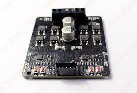
SmartElex 15D Motor Driver
The SmartElex 15D is a dual channel motor driver with a continuous output of 15 amps and peak currents of 30 amps (10sec) per channel. The motor driver can be operated in radio control, analog, TTL serial, and PWM modes. A variety of operating modes are available, including a mixed and independent radio control mode, as well as analog and PWM modes.
Operating modes allow for operation, such as switching between radio controls and PWM mode or switching between any of 4 modes via 4 position DPDT mode switch. MOSFETs are switched at a frequency of 16 kHz to provide silent operation and eliminate unwanted whining.
It also has a microcontroller unit that provides smart features like different input modes, current restrictions, and thermal protection. When the temperature of the board hits 80 degrees, the motor speed is reduced by half, and once the temperature drops below 70 degrees, the speed returns to normal. At 100 degrees, the motor driver shut down.
Features:
- Supplying 15 amps continuous with peak currents up to 30 amps (10 Sec) per channel
- Support motor voltage from 7V to 28V.
- Onboard Low Internal resistance MOSFETs are switched at 16 kHz frequency.
- Over-current protection and indication.
- Thermal protection.
- Multiple input modes: RC, Analog, PWM, Serial Packetized.
- Onboard push buttons for test and manual operation.
Specifications:
| Sr.No | Parameters | Range |
| 1 | Input Voltage | 7-28V |
| 2 | Maximum Continous Current Imax | 15A |
| 3 | Peak Motor Current for 10s | 35A |
| 4 | VIOH(Logic Input-High Level) | 3-5.5V |
| 5 | VIOL(Logic Input-Low Level) | 0.5V |
| 6 | PWM Frequency | 16KHz |
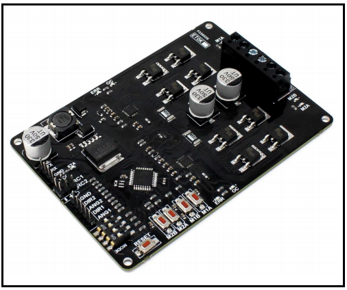
Pinout Diagram:

- Power Input: Connect to a 7V-28V Battery or Power Supply.
- Motor 1 and Motor 2 Terminal: Connect Motor 1 to Motor 1 Terminal. Connect Motor 2 Motor 2 Terminal.
- Mode Selection: It uses to set the operating mode and options.
- Error (ERR) and Over Current (OC) LEDs: Error LED glows when Under-Voltage Lockout (Input Voltage less than 7V). Overcurrent LEDs glow due to current greater than 35 AMP.
- RC Input: 2 channel Radio Controller receiver connected to these pins.
Control Mode:
SmartElex 15D supports four different types of input modes:
- PWM mode
- Radio Control (RC)
- Analog
- Serial Packetized
- PWM mode:
There are a variety of methods for controlling the speed of DC motors, but one of the most basic and straightforward is to employ Pulse Width Modulation. Pulse width modulation (PWM) is an excellent way to manage the amount of power given to a load without wasting any. The advantage of using pulse width modulation to operate a small motor is that the switching transistor’s power loss is minimal because the transistor is either fully “ON” or totally “OFF.” As a result, the switching transistor’s power consumption is much reduced, resulting in a linear form of control with improved speed stability.
Moreover, the amplitude of the motor voltage remains constant, ensuring that the motor is constantly operating at full capacity. As a result, the motor may rotate at a considerably slower speed without stalling.
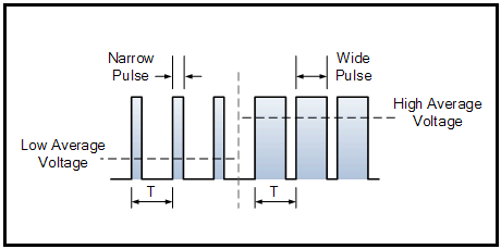
Fig1.0. Pulse Width Modulated Wave
- RC mode:(Radio Control Mode):
In this mode, the RC1 and RC2 channels of the receiver, or anything that can create servo signals, are utilized to control the speed and direction of the SmartElex 30D in Radio Control mode.
- Analog Mode:
The Analog voltage controls the speed and direction of the motor in Analog input mode. The voltage range for the analog input is 0V to 5V.
- Serial Mode:
In Serial mode, the SmartElex 30D’s TX pin is connected to the Controller’s Rx pin, and the Controller’s Rx pin is connected to the SmartElex 30D’s TX pin. Switches can be used to set the baud rate. 9600, 19200, 38400, and 57600 baud speeds are supported.
Refer to the below table to set the DIP switch settings for each mode and the function for the input pin,
| SWITCH/MODES | DIP SWITCH 1 | DIP SWITCH 2 | DIP SWITCH 3 | DIP SWITCH 4 |
| RC | 0 -Independent 1- Mixed | 0 -Linear 1- Exponential | 0 | 0 – RC |
| ANALOG | 0 -Independent 1- Mixed | 0 -Linear 1- Exponential | 0 | 1 – ANALOG |
| PWM | 0 -Independent 1- Mixed | 0 -Linear 1- Exponential | 1 | 0 – PWM |
| SERIAL | 0 0-96001 0-38400 | 0 0-192001 0-57600 | 1 | 1 – SERIAL |
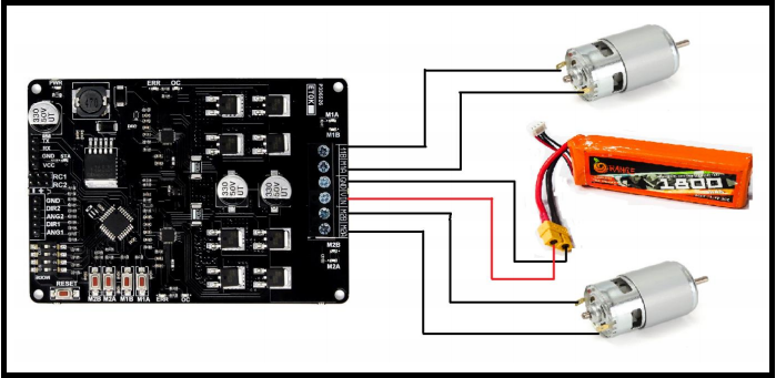
Hardware required:
- SmartElex 15D Smart Motor Driver
- DC Motors-x2(30RPM,12V)
- Connecting Wires
- Battery(12V)-(Forgiving Power supply to the Motor Driver)
- Flysky FS-i6X 2.4GHz 6CH AFHDS 2A RC Transmitter with FS-iA10B 2.4ghZ 10CH Reciever
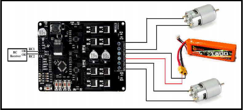
Connections and wiring:
How to operate the Motor in RC Mode:
SmartElex 15D can be used with batteries or power supplies. With an input voltage range of 7V to 28V, the input power is linked to the center power terminals to the motor driver pins VIN and GND. The input current is determined by the motors utilized and the load they are subjected to. Using undersized wire can cause the wire to become heated, as well as high temperatures on the SmartElex 30D.
The SmartElex 15D’s main power connections are located on the board’s backside. Large black screw terminal connections were constructed. These terminals can handle wire gauges ranging from 10 to 28. Twinned 10 gauge wire connections to the battery terminals can be made with stranded wire. If your design will be operating both motors near or above the 15 amp continuous limit, this is usually a smart idea. All applications should be able to use single 12 gauge wires for motor connections.
After connecting the power to the SmartElex 15D motor driver, connect the FS-iA10B 2.4ghZ 10CH Reciever module to the SmartElex motor driver’s RC channels as indicated below. The next stage is to link the Transmitter and Receiver together.
How to Bind the Transmitter with the Receiver Module:
The process of binding Flysky FS-i6X 2.4GHz 6CH AFHDS 2A RC Transmitter with FS-iA10B 2.4ghZ 10CH Reciever is given below:
- Turn on the receiver and press the bind button at the same time. It has reached bind mode if the receiver led is flashing.
- The transmitter will immediately return to the previous menu after successful binding. The receiver’s LED will cease flashing and remain solid if the binding is successful.
- Verify that all of the models and receivers function properly. If anything doesn’t work as it should start over from the beginning.
After the binding move, the throttle of the transmitter to operating the motor in the forward and reverse directions.
Conclusion:
Hope this blog helps you to understand how to use the SmartElex Motor Driver in RC Mode We, MATHA ELECTRONICS, will come back with more informative blogs.