
How to use ADC in STM32F103C8T6? STM32 ADC Tutorial
In this tutorial, I’ll demonstrate how to measure the input analogue voltages using the STM32F103C8T6 Blue Pill Board’s ADC. In this project, I’ll use the LCD to display the ADC findings.
Why Do We Need This System?
In practically all embedded applications, a Microcontroller must be interfaced with at least one Sensor. It might be a temperature or location sensor. If there is one thing we are certain of when it comes to sensors, it is that they are almost always analogue in nature. In other words, a sensor generates an analogue voltage by reading an analogue value from the environment, such as a temperature.

Analogue values, however, are not compatible with microcontrollers because they are digital “beings” (such as the STM32F103C8T6 or Arduino). Therefore, we must first convert the analogue value to a digital value before sending it to the microcontroller for extra processing or analysis. Analog to digital converters are used for this.
If you’ve worked with 8051 microcontrollers, you might have converted analogue input signals into digital numbers using an external ADC IC, like the ADC0804 IC. The majority of modern microcontrollers, such as the Arduino and STM32F103C8T6, do, however, have an integrated ADC. As a result, we don’t need any additional components. It only requires setting up the internal ADC and converting the analogue signals to digital values.
In this project/tutorial, I’ll demonstrate how to set up an analogue pin to receive voltage from a potentiometer, the most basic source of adjustable analogue voltage, convert the voltage to a digital value using an ADC, and display the result on an LCD.
Components Required
- STM32F103C8T6 MCU based STM32 Blue Pill Board
- 16×2 LCD Display
- 10KΩ POT x 2
- USB to UART Converter (if programming through UART)
- Connecting Wires
ADC in STM32 Blue Pill
The ADC of the STM32F103C8T6 MCU is a Successive Approximation Type ADC with a 12-bit resolution, as can be seen in the datasheet. Up to 16 external channels can have their analogue signals measured by the MCU.
The STM32 Blue Pill board’s ADC, however, is configured for 10 Channels, which enables 10 Analog Input pins to measure 10 distinct analogue voltages.
How to use ADC in STM32F103C8T6?
As was already noted, the ADC in the STM32 Blue Pill has a resolution of 12 bits. The ADC value range for the STM32F103C8T6 is therefore 0 to 212 – 1, or 0 to 4095. Based on the analogue voltage, value will gradually increase.
The voltage/Step or resolution can be calculated using the formula below.
Voltage / Step = Reference Voltage / 212
The reference voltage is typically 3.3 V. The lowest voltage change that may be seen is Voltage / Step = 3.3 / 4096 = 0.8056 mV / Step.
Now, the following formula can be used to calculate the input analogue voltage:
Voltage / Step = 3.3 / 4096 = 0.8056 mV / Step
Now, the Input Analog Voltage can be calculated as follows:
Input Voltage = ( ADC Value / ADC Resolution ) * Reference Voltage
Circuit Diagram
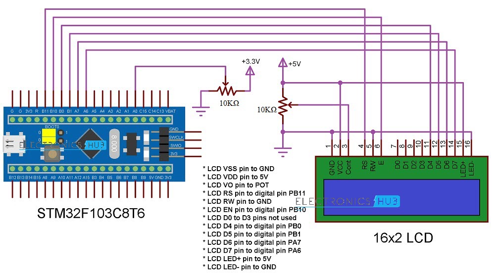
The circuit schematic for the project to configure the ADC in the STM32F103C8T6 is displayed in the following image.
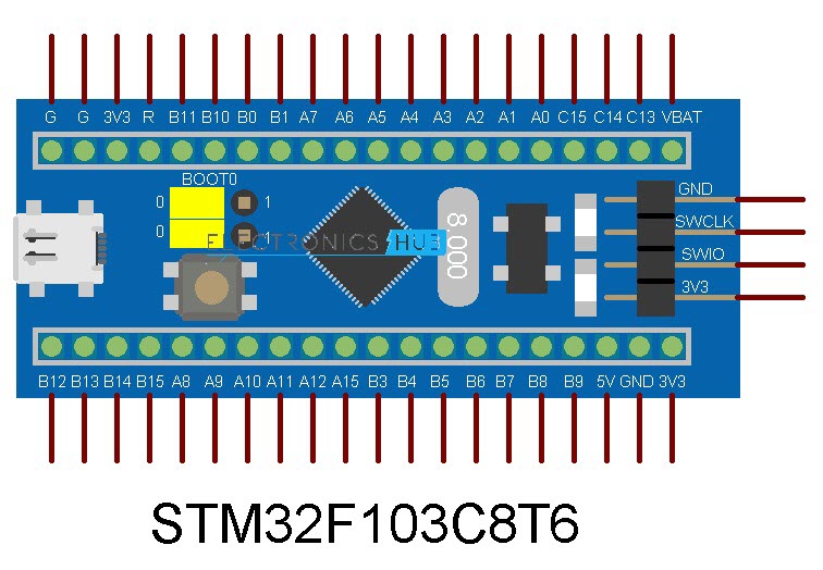
Use the following image as a guide if the STM32 Blue Pill Board pins used in the circuit schematic are unclear.
Circuit Explanation
The STM32 Blue Pill Board has 10 analogue inputs, as was already indicated. They are PB0 and PB1, as well as PA0 through PA7 (ADC0 to ADC7) (ADC8 and ADC9).
Any of the Analog Input Channels may be used in your project. I’ll be using ADC0, or the PA0 pin, as the analogue input pin for this demonstration. The centre (wiper) terminal of a 10K potentiometer is attached to this pin, while the other two terminals of the POT are connected to 3.3 V and GND.
A 162 LCD display is the output device I’m utilising. The connections between the STM32 Blue Pill Board and the 16×2 LCD have already been described in the project “Interfacing 16×2 LCD with STM32F103C8T6.” Here too, I’m employing the same linkages.
Programming STM32 Blue Pill
You do not need a USB to UART Converter if you have already completed my “Application STM32 Blue Pill over USB” instruction because you may upload the programme using the onboard USB.
First, initialise the LCD and analogue input pins in the programme. Initialize the LCD after that, and display some introduction data. Use the analogRead function in the loop section to read the analogue voltage from the analogue input pin (PA0), and then store the result in the analogVal variable.
You can now determine the input voltage using the formula above. To store the estimated input voltage value, use a Float variable.
float inputVoltage = ((float) analogVal) / 4096 * 3.3
Display the calculated Analog Voltage on the LCD along with the calculated ADC Value. You can continuously vary the POT and the corresponding analogue voltage will be read by the ADC in STM32F103C8T6 and calculated voltage.
Code
| /* * LCD VSS pin to GND * LCD VDD pin to 5V * LCD VO pin to POT * LCD RS pin to digital pin PB11 * LCD RW pin to GND * LCD EN pin to digital pin PB10 * LCD D0 to D3 pins not used * LCD D4 pin to digital pin PB0 * LCD D5 pin to digital pin PB1 * LCD D6 pin to digital pin PA7 * LCD D7 pin to digital pin PA6 * LCD LED+ pin to 5V * LCD LED- pin to GND */ #include <LiquidCrystal.h> const int rs = PB11, en = PB10, d4 = PB0, d5 = PB1, d6 = PA7, d7 = PA6; LiquidCrystal lcd(rs, en, d4, d5, d6, d7); const int analogInput = PA0; void setup() { lcd.begin(16, 2); lcd.clear(); lcd.setCursor(0, 0); lcd.print(“Electronics Hub”); lcd.setCursor(0, 1); lcd.print(” ADC in STM32 “); delay(2000); lcd.clear(); } void loop() { int analogVal = analogRead(analogInput); float inputVoltage = (float(analogVal)/4096) * 3.3; lcd.setCursor(0, 0); lcd.print(“ADC Value:”); lcd.print(analogVal); lcd.setCursor(0, 1); lcd.print(“Voltage:”); lcd.print(inputVoltage); } |
Conclusion
Hope this blog helps you to understand how to use ADC in STM32F103C8T6. STM32 ADC Tutorial. We, MATHA ELECTRONICS will come back with more informative blogs.