
How to use Arduino’s Internal EEPROM?

This article will show us about the EEPROM, a unique kind of memory. Additionally, we’ll look at the internal EEPROM of the Arduino and how to use it. We’ll create a simple circuit and learn how to use the Arduino EEPROM’s READ and WRITE commands.

Introduction
The topic of memory in computers is fascinating. Memory is, to put it simply, a tool for storing data. All computers require memory to store data either permanently or momentarily, whether they are massive Microprocessor-based systems or small Microcontroller-based Embedded Devices.

Take Arduino as an illustration. The Arduino UNO board includes three different types of memory, according to the specifications listed in this tutorial on the Arduino UNO Pinout:
- 32 KB of Flash
- 2 KB of RAM
- 1 KB of EEPROM
Leaving the size numbers aside, RAM is a temporary memory, while Flash and EEPROM are types of permanent memories. What does this mean, exactly? One sort of memory that can continue to hold data after the power is turned off is known as a permanent memory.
On the other hand, temporary memory is employed to store transient data while the application is executing and it can keep such values till power is connected
Memories can be categorized into two categories according to their dependence on power:
- Non-volatile Memory
- Volatile Memory
The non-volatile memory includes Flash and EEPROM, where Flash is used to store program code and EEPROM is used to store small amounts of data (like a sensor data log or hardware information). Even if the power is cut off, the data in both of this memory will remain intact
RAM is a volatile memory, meaning that if the power is turned off, the data is lost.
What is EEPROM?
Let’s now concentrate on the relevant Memory. Electrically Erasable Programmable Read Only Memory, often known as EEPROM or E2PROM, is the replacement for prior generations’ ROM (Read Only Memory), PROM (Programmable Read Only Memory), and EPROM (Erasable Programmable Read Only Memory).
Let’s take a quick history lesson on memories before moving on. ROM, or read-only memory, is a type of non-volatile memory used to store data permanently, such as the firmware of an embedded device.
Since initial ROMs are factory-programmed, it is impossible to alter their contents. Additionally known as MROM, these (Masked Read Only Memory).

Then the Programmable Read-Only Memory, or PROM, appeared. Although they can be programmed by the end user (using a unique tool called a PROM Programmer), it can only be done once.
EPROM was created to solve the “one-time programmable” PROM issue. Erasable Programmable Read Only Memory is what it stands for. The memory can be programmed similarly to a PROM and can be deleted by placing it under a powerful UV light.
The EPROM memory ultimately becomes worn out through frequent exposure to bright light, commonly from a mercury vapor lamp, limiting the number of erase cycles to under 1000.
The memory may now be electrically wiped while it is still installed in the system thanks to the development of EEPROM, or Electrically Erasable Programmable Read Only Memory (which was not possible with EPROM).
NOTE: Modern Flash Memory is a form of EEPROM and is used in devices like Memory Cards, USB Flash Drives, Solid State Drives, Microcontrollers, etc.
Modern microcontrollers employ EEPROMs to store tiny data and Flash Memory to store the firmware (like parameters, Device ID, History, etc.).
EEPROM in Arduino
We can preserve basic information like default settings, the status of an LED, or the status of a relay even when the power is off thanks to the use of EEPROM in our Arduino projects.
With Arduino, there are two ways to use EEPROM. Using the internal EEPROM of the Arduino is the first and simplest method. The second choice is to include an external EEPROM IC, such as the well-known ATMEL AT24 family. In this tutorial, let’s concentrate on the Arduino’s internal EEPROM.

Since the Internal EEPROM is a microcontroller feature rather than a board feature, all Arduino boards, including the UNO, Mega, and Nano, include some Internal EEPROM.
The internal EEPROM size for some popular ATMEL microcontrollers used in different Arduino boards is displayed in the table below.
| Microcontroller | Boards | Size |
| ATmega328P | UNO, Nano, Mini | 1024 Bytes (1 KB) |
| ATmega2560 | Mega | 4096 Bytes (4 KB) |
| ATmega168 | Nano | 512 Bytes |
Arduino EEPROM Library
The internal EEPROM of the Microcontroller on the Arduino Board can be read from and written to using a special library called the EEPROM Library. You don’t need to download anything additional; it is included with IDE by default.
The EEPROM library for Arduino offers the following five really helpful features:
- EEPROM.read() – Read a byte from EEPROM.
- EEPROM.write() – Write a byte to EEPROM.
- EEPROM.update() – Write a byte to EEPROM only if the current value is different to previous value.
- EEPROM.get() – Read any datatype from EEPROM (float or struct or any datatype).
- EEPROM.put() – Write any datatype to EEPROM (float or struct or any datatype).
The EEPROM Library has examples in the Arduino IDE. To learn more, look through those.
Test Circuit: Remember the State of Relay
Both EEPROM in general and EEPROM in Arduino have been the subject of a lot of theory. Only once we see how this idea is put into practise does it all make sense. So let’s construct a tiny circuit to evaluate the EEPROM functionality of the Arduino. Can Arduino Remember the State of Relay? is the name of the application.

I’ll use a push button to switch on or off a relay in this test circuit. When the button is pressed, I will also simultaneously record the status of the Relay in the EEPROM. As a result, whenever the Arduino is restarted, it first retrieves the Relay’s previous state from the EEPROM and sets the relay to that state.
Circuit Diagram
The circuit diagram for testing the Arduino EEPROM is displayed in the accompanying figure.
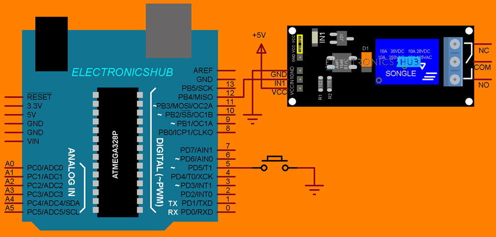
Circuit Diagram for Arduino EEPROM Test Circuit
Code
You don’t require any additional libraries, as I just stated. Simply include the “EEPROM.h” header file in your code is all that is required.
| #include <EEPROM.h> | |
| #define buttonPin 5 | |
| #define relayPin 12 | |
| int relayState; | |
| int buttonValue; | |
| int buttonState; | |
| int lastButtonState = LOW; | |
| long lastDebounceTime = 0; | |
| long debounceDelay = 50; | |
| void setup() | |
| { | |
| pinMode(buttonPin, INPUT_PULLUP); | |
| pinMode(relayPin, OUTPUT); | |
| checkrelayState(); | |
| } | |
| void loop() | |
| { | |
| buttonValue = digitalRead(buttonPin); | |
| if(buttonValue != lastButtonState) | |
| { | |
| lastDebounceTime = millis(); | |
| } | |
| if((millis() – lastDebounceTime) > debounceDelay) | |
| { | |
| if(buttonValue != buttonState) | |
| { | |
| buttonState = buttonValue; | |
| if(buttonState == LOW) | |
| { | |
| relayState = !relayState; | |
| } | |
| } | |
| } | |
| digitalWrite(relayPin, relayState); | |
| EEPROM.update(0, relayState); | |
| lastButtonState = buttonValue; | |
| } | |
| void checkrelayState() | |
| { | |
| relayState = EEPROM.read(0); | |
| if(relayState == 1) | |
| { | |
| digitalWrite(relayPin, HIGH); | |
| } | |
| if(relayState == 0) | |
| { | |
| digitalWrite(relayPin, LOW); | |
| } | |
| } |
Conclusion
I hope all of you had understand the basics of EEPROM in Arduino. We MATHA ELECTRONICS will be back soon with more informative blogs soon.