
How to use SPI in STM32F103C8T6?
This article will demonstrate the basics of using SPI on an STM32 Blue Pill Board powered by the STM32F103C8T6 MCU. One master device and zero or more slave devices are required for SPI communication. So, I’ll set up the STM32 as the SPI Master and the Arduino UNO as the SPI Slave in order to show you how SPI works in the STM32F103C8T6.
Introduction
The term “SPI” stands for “Serial Peripheral Interface,” and it is one of the most used protocols for exchanging information between a microcontroller and various add-on components.
The standard number of wires required to implement SPI Communication is four, though this can be reduced. In this guide, I’ll be utilising SPI Communication, which uses a total of four wires.
- SCLK –> Serial Clock
- MOSI -> Master Output Slave Input (Data from Master to Slave)
- MISO -> Master Input Slave Output (Data from Slave to Master)
- SS -> Slave Select
The following picture illustrates the elementary SPI Interface used by a Master and a Slave. Corresponding signal directions are also depicted in the figure.

By setting the SS signal to LOW, a specific slave can be activated. Every slave device in a multi-slave setup receives its own unique SS Signal from the master, and at any given time, only one of the slaves can be operational.
Internally, the hardware of SPI Communication is relatively basic. It is made up of a Data Latch and a Shift Register. Keep in mind that the SCLK Line’s Clock Signal is always generated by the Master device.

SPI in STM32F103C8T6
Both of the STM32F103C8T6 MCU’s SPI ports provide full duplex and simplex operation at speeds of up to 18 Mbits/s. Both SPI Interfaces are color-coded purple on the STM32 Blue Pill Board’s pinout diagram.
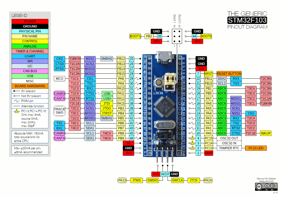
There are two distinct pinouts for the SPI1 Interface. The STM32F103C8T6 MCU’s SPI pins are listed below.
| SPI Signal | Pins | Alternative Pins | |
| SPI1 | SS1 | PA4 | PA15 |
| SCLK1 | PA5 | PB3 | |
| MISO1 | PA6 | PB4 | |
| MOSI1 | PA7 | PB5 | |
| SPI2 | SS2 | PB12 | – |
| SCLK2 | PB13 | – | |
| MISO2 | PB14 | – | |
| MOSI2 | PB15 | – |
For the STM32 SPI Tutorial, I will be using the first set of pins of SPI1.
SPI in Arduino
As mentioned earlier, I am going to use Arduino UNO as the SPI Slave device. You can use any other SPI Devices like any Sensors or Memory ICs but I chose to use an Arduino as you can easily decode the SPI data and further do something extra like light up an LED or display the information on an LCD, which you cannot do with an EEPROM IC.

Speaking of SPI in Arduino, the Digital IO pins 10 through 11 are wired to the SPI Interface. The following table lists out the SPI pins in Arduino UNO.
| SPI Signal | Arduino Pin |
| SS | Digital IO 10 |
| MOSI | Digital IO 11 |
| MISO | Digital IO 12 |
| SCK | Digital IO 13 |
How to use SPI in STM32F103C8T6?
The STM32 Blue Pill Board acts as the SPI Master and the Arduino UNO acts as the SPI Slave in this demonstration of SPI in the STM32F103C8T6. I’ll be using the on-board LEDs and external Push Buttons to connect the two boards together.
In response to a push on the STM32-connected push button, Arduino’s indicator light will illuminate. Similarly, activating the LED on the STM32 Blue Pill Board requires pressing the Push Button attached to the Arduino UNO.
Both the STM32 Blue Pill Board and the Arduino UNO can interface with 16×2 LCD displays to show additional data.
Components Required
- STM32F103C8T6 MCU based STM32 Blue Pill Board
- Arduino UNO
- 2 x Push Buttons
- 2 x 10 KΩ Resistors
- Connecting Wires
- USB to UART Converter (if STM32 is programmed via UART)
- USB Cable for Arduino UNO
Circuit Diagram
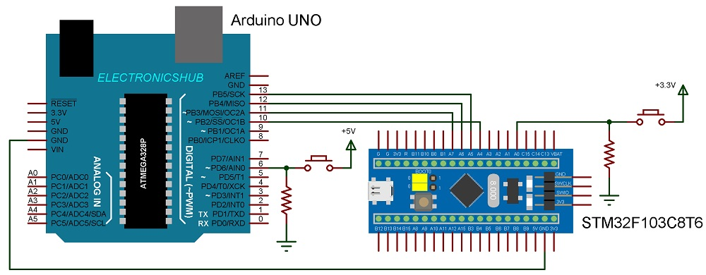
The following picture demonstrates the STM32 SPI Tutorial by showing the connections between the STM32 and Arduino.
Connections Explained
The SPI Pins on the STM32 Board and the Arduino UNO must be located first. Then connect the STM32’s data input (MOSI, PA7) to the Arduino’s data input (MISO, Digital IO 12), the STM32’s clock input (SCLK, PA5) to the Arduino’s clock input (SCK, Digital IO 13), and the STM32’s serial output (SS, Digital IO 14). (Digital IO 10).
The SPI-related pins of the Arduino UNO and the STM32 are compared in the table below.
| SPI Pin | STM32 Blue Pill | Arduino UNO |
| SS | PA4 | Digital IO 10 |
| SCLK | PA5 | Digital IO 13 |
| MISO | PA6 | Digital IO 12 |
| MOSI | PA7 | Digital IO 11 |
Finally, hook up a push button to the STM32’s PA0 pin. Put a 10K resistor in series with this pin and connect it to the ground. The push button’s opposite end must be connected to 3.3V. Connect the GND end of a 10K resistor to Digital IO pin 6 on Arduino and the push button end of a push button to Digital IO pin 6 on Arduino. Plug the push button’s other end into a source of 5V.
Programming STM32 for SPI Communication
Let me get started with the STM32 programming, please. Make LED, button, and slave pick pin outputs and inputs, correspondingly.
Start Serial Peripheral Interface (SPI) communication and divide by 16 to slow the SPI clock with the macro SPI CLOCK DIV16. This means that the SPI clock will be 4.5 MHz, the result of dividing the main clock (72 MHz) by 16. The slave is not yet connected, hence the SS pin should first be set to HIGH.
In a never-ending cycle, collect the Button’s current state and transmit it using SPI. While transmitting its data, the slave also stores it in a variable.
Based on the data, adjust the brightness of the LED.
Code
| #include<SPI.h> #define SS PA4 #define ledPin PC13 #define buttonPin PA0 void setup (void) { pinMode(SS, OUTPUT); pinMode(ledPin, OUTPUT); pinMode(buttonPin, INPUT); SPI.begin(); SPI.setClockDivider(SPI_CLOCK_DIV16); digitalWrite(SS, HIGH); digitalWrite(ledPin, LOW); } void loop(void) { int masterSend, masterReceive; masterSend = digitalRead(buttonPin); digitalWrite(SS, LOW); masterReceive = SPI.transfer(masterSend); delay(500); digitalWrite(SS, HIGH); if (masterReceive == HIGH) { digitalWrite(ledPin, HIGH); } else { digitalWrite(ledPin, LOW); } } |
Programming Arduino for SPI Communication
With Arduino in mind, set the LED and button pins to output and input modes, respectively. Make MISO an output as well.
When using Serial Peripheral Interface (SPI), an Arduino often takes on the role of Master. However, for this lesson, we need Arduino to take on the role of slave. You must change the SPCR register in order to use Arduino’s SPI in a slave configuration.
With the SPI Interrupt turned on, an interrupt will be triggered whenever the SPI receives data. The data is stored in a variable in SPI’s Interrupt Service Routine.
The button’s state is read in the loop and communicated through SPI. As an added measure, the ISR analyses the data it has received and turns the LED on or off accordingly.
Code
| #include<SPI.h> const int ledPin = 13; const int buttonPin = 6; volatile boolean received; volatile int slaveReceive, slaveSend; void setup() { pinMode(ledPin, OUTPUT); pinMode(buttonPin, INPUT); pinMode(MISO, OUTPUT); digitalWrite(ledPin, LOW); /* Turn on SPI in Slave Mode */ SPCR |= _BV(SPE); received = false; /* Interupt ON is set for SPI Commnunication */ SPI.attachInterrupt(); } /* SPI ISR */ ISR (SPI_STC_vect) { /* Value received from master STM32F103C8T6 is stored in variable slaveReceive */ slaveReceive = SPDR; received = true; } void loop() { slaveSend = digitalRead(buttonPin); /* Send the slaveSend value to master STM32F103C8T6 via SPDR */ SPDR = slaveSend; if(received == true) { if(slaveReceive == HIGH) { digitalWrite(ledPin, HIGH); } else { digitalWrite(ledPin, LOW); } } } |
WARNING: Before you transfer the application to the STM32 (through USB to UART or direct USB Bootloader), you must first connect it to your PC. After making any necessary adjustments in the Arduino IDE, the next step is to upload the software to the Arduino UNO and then disconnect it.
Conclusion
Hope this blog helps you to understand How to use SPI in STM32F103C8T6? We, MATHA ELECTRONICS will come back with more informative blogs.