
How to Interface Piezoelectric Sensor with Arduino
Sensors are devices that are used to detect or sense various physical quantities in the environment. Light, heat, motion, moisture, pressure, vibrations, all may be used as inputs. Normally, the output is an electrical signal proportional to the applied input. The output signal is either utilized to calibrate the input or it is sent over a network for additional processing. There are various kinds of sensors depending on the input to be measured.
Vibration detection and measurement can be employed in a variety of applications, including decision-making circuits and alarm circuits. The Piezo electric method is the most effective way to detect vibration. The vibration sensor, also known as a Piezo electric vibration detector, is a low-cost sensing device that electronic designers, engineers, and hobbyists may easily achieve. In this blog, we’ll talk about the piezoelectric sensor, its features, and how to interface it to an Arduino.
PIEZO ELECTRIC SENSOR:
A piezoelectric sensor is a sensor that works on the basis of piezoelectricity. When mechanical stress is applied to a material, piezoelectricity occurs, and electricity is created. Not every substance has piezoelectric properties.There are various types of piezoelectric materials. Examples of piezoelectric materials are natural available single crystal quartz, bone etc…and Artificially manufactured like PZT ceramic etc

Piezoelectricity is a phenomena in which a substance generates electricity when mechanical stress is applied to it. A piezoelectric sensor is one that measures differences in acceleration, strain, pressure, and force by turning them into electrical charge. The piezoelectricity generated is proportional to the stress applied to the strong piezoelectric crystal’s substrates.
Force and non-electrical physical variables that can be converted into electricity are measured with piezoelectric sensors. Wide bandwidth, high sensitivity, high signal-to-noise ratio, simple structure, dependable operation, and lightweight are some of its benefits. The drawback is that some piezoelectric materials require moisture protection, and the output DC responsiveness is low. To overcome this issue, high input impedance circuits or charge amplifiers are required.
SPECIFICATIONS:
- Voltage Sensitivity (open-circuit, baseline): 1.1 V/g.
- Charge Sensitivity (baseline): 260 pC/g.
- Upper Limiting Frequency (+3 dB): 42 Hz.
- Resonance Frequency: 75 Hz.
- Voltage Sensitivity (open-circuit, at resonance): 6 V/g.
- Wide dynamic range:001Hz~1000MHz
- Laminated for higher voltage output
- Breadboard friendly leads.
- Operating Temperature: 0ºC to 85ºC
- Storage Temperature: -40ºC to 85 ºC
- Dimensions: 6.9 x 3.9 x 0.8 cm
- Weight: 10 Grams
FEATURES OF PIEZO ELECTRIC SENSOR:
Piezoelectric sensors have the following characteristics;
- Flexible PVDF Piezo Polymer Film
- Flex, Touch, Vibration and Shock measurements
- High strength
- High voltage output
- Elastic compliance
- Wide frequency range
- Impact resistance
- High mechanical strength
- High stability
- Standard grove socket
- Adjustable sensitivity
- Withstands High Impact
PIEZOELECTRIC VIBRATION SENSOR PINOUT:
This Module has 4 pins:
- VCC: Module power supply – 3.3V to 5V
- GND: Ground
- D0: Digital Output
- A0: Analog Output

HOW DO PIEZO ELECTRIC SENSOR WORK?
Piezo Vibration Sensor is used for measurements of flexibility, vibration, impact, and touch. This module is based on the PZT film sensor LDT0-028. When the sensor moves back and forth, the voltage comparator inside the sensor induces a certain voltage (up to +/-90V is created). Therefore a wide dynamic range (0.001Hz~1000MHz) ensures excellent measuring performance and high reliability. The onboard potentiometer with a screw in the sensor is used to adjust its sensitivity. A simple resistor should get the voltage down to ADC levels.

The basic piezo vibration sensor works on the principle of the piezoelectric effect. A piezoelectric crystal placed between two metal plates arranged in a perfect balance does not conduct an electric current. When any Mechanical stress or force is applied on the material by the metal plates, which forces the electric charges within the crystal out of and appear on opposite sides of the crystal face. As a result, these metal plate collects charges, further used to produce a voltage and send an electrical current through a circuit–generating piezoelectricity. Thus this Small Horizontal low-cost cantilever-type vibration sensor is loaded by a mass to offer high sensitivity at low frequencies.

HARDWARE REQUIRED:
- Arduino board.
- Piezoelectric pressure sensor.
- LED
- 2 MΩ resistor.
CIRCUIT DIAGRAM:
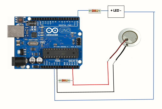
Here the positive lead of the sensor, denoted by the red wire, is linked to the Arduino board’s A0 analogue pin, while the negative lead, denoted by the black wire, is connected to ground. To limit the voltage and current produced by the piezoelectric device and protect the analogue input from undesired vibrations, a 2 MΩ resistor is connected in parallel to it. The anode of the LED is linked to the Arduino’s digital pin D13, while the cathode is connected to ground.
A threshold value of 100 is set to the circuit so that the sensor is not activated for vibrations less than the threshold. Using this, we can eliminate unwanted small vibrations. When the output voltage generated by sensor element is greater than the threshold value the LED changes its state i.e. if it is in the HIGH state it goes to LOW. If the value is lower than the threshold LED doesn’t change its state and remains in its previous state.
The circuit is configured to a threshold value of 100, which prevents the sensor from being engaged for vibrations below the threshold. We can reduce undesirable tiny vibrations this way. When the output voltage provided by the sensor element exceeds the threshold value, the LED changes state, i.e. it goes from HIGH to LOW. If the value is less than the threshold, the LED does not change status and remains in the same state as before.
CODE FOR ARDUINO:
| int sensoroutput = 3; // the analog pin connected to the sensor int ledoutput = 0; // pin connected to LED int THRESHOLD = 100; void setup() { pinMode(ledPin, OUTPUT); // this function is used to declare led connected pin as output } void loop() { int value = analogRead(sensoroutput); // function to read analog voltage from sensor if (value >= THRESHOLD) // function to check voltage level from sensor { digitalWrite(ledoutput, HIGH); delay(100); // to make the LED visible } else digitalWrite(ledoutput, LOW); |
APPLICATIONS OF PIEZO ELECTRIC SENSOR:
- Shock detection.
- Motion detection
- Door knock sensor
- Acceleration measurement system
- Force measurement system
- pressure measurement system
- Microphone used sound sensor to convert it into electrical form.
lighters for cigarette - testing of high voltage equipment’s And there are thousands of applications of piezo electric sensor
- Piezoelectric sensors are also used for ultrasound imaging.
- These sensors are used for optic measurements, micro moving measurements, electro acoustics etc…
CONCLUSION:
Thus, this is all about what is a piezoelectric sensor, properties, specifications and also simple interfacing of the sensor using Arduino board.
looking for silicon tube pressure monitoring for our peristaltic pump
I want two set of sensor and the board and display to apply it like a load cell weighing