
Many fingerprint sensors are available on the market, and we commonly use R305/R307 Optical fingerprint sensors in projects such as Attendance systems and Biometric Security systems. We also employed an advanced fingerprint sensor, such as the GT511C3, which has a high level of accuracy and a quick response time. It detects fingerprints using a camera image processing technology rather than the optical method.

In this blog, we discuss the details and specifications of the R502/R503 Capacitive Fingerprint Sensor, as well as how the Capacitive Fingerprint Sensor works. Apart from that, we’ll use the Adafruit Library to connect the R502/R503 Capacitive Fingerprint Sensor to Arduino, and then learn how to enroll and test fingerprints.
Hardware Required
- Arduino UNO/Nano Board
- R503 Optical fingerprint sensors
- Jumper Wires
Capacitive Fingerprint sensor
Capacitive fingerprint sensors work by discharging stored electricity only at the spots where your fingerprint ridges hit the sensor’s grid of small capacitors. Capacitive fingerprint sensors use the conductivity of the human finger to generate an electrostatic field and then a digital image. Once a digital image of a fingerprint has been recorded, the associated processor can examine it for unique characteristics.
R502/R503 Capacitive Fingerprint Sensor
The R502/R503 is the most widely used and cheapest capacitive fingerprint sensor on the market. The chip was created by combining image gathering and algorithm chips. The best thing about R502/R503 is that it responds to different finger circumstances, such as dry fingers, moist, light texture, or aged fingertips with a high recognition rate. When comparing R502 to R503, the distinction is that R502 is thinner and smaller.

The fingerprint sensor operates at 3.3V and consumes 18mA during fingerprint acquisition and 2uA on average during standby. It communicates using the RS232 UART interface at a baud rate of 57600bps by default. It has a maximum capacity of 200 fingerprints. Arduino, Android, Windows, and Linux are all supported by the R502/R503 fingerprint module.
Pinout
There is a total of 6 wires basically pinout of R502/R503 Fingerprint Sensor which is as follows.

Interfacing R502/R503 Capacitive Fingerprint Sensor with Arduino
Let’s look at how to connect an R502/R503 Capacitive Fingerprint Sensor to an Arduino. The connection diagram is given below
Connection Diagram
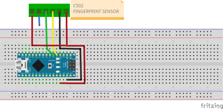
- RED WIRE : VCC- (3.3V-5V)
- BLACK WIRE: GND
- YELLOW WIRE: TXD—-D2
- GREEN WIRE: RXD——D3
- BLUE WIRE: interrupt (not connected )
- WHITE WIRE: (3.3V-5V)
Connecting the Sensor With Arduino
- Connect the 3.3V pin of the Arduino UNO to the Vcc and Power Supply pins (Green and White Wires, respectively) of the fingerprint scanner.
- Connect the Arduino’s GND pin to the Ground pin (Red Wire) of the scanner.
- Connect the Arduino’s Digital Pin 3 to the Rx Pin (Black Wire) of the Scanner.
- Connect the Arduino’s Digital Pin 2 to the Tx Pin (Yellow Wire) of the scanner.
- Finally, attach the IRQ Pin (Blue Wire) of the scanner to the Arduino’s Digital Pin 6.
Conclusion:
I hope all of you have understood how to interface the R502/R503 Capacitive Fingerprint Sensor with Arduino. We MATHA ELECTRONICS will be back soon with more informative blogs.