
IR Sensor : Circuit Diagram, Types Working with Applications
Infrared technology is employed in everyday life as well as in industry for various of purposes. The key advantages of IR sensors are their low power consumption, simple construction, and useful functionality. IR signals are undetectable to the naked eye. In the electromagnetic spectrum, IR radiation can be found in the visible and microwave ranges.
Wavelengths of these waves typically range from 0.7 m 5 to 1000 m. Near-infrared, mid-infrared, and far-infrared are the three sections of the IR spectrum. The wavelength extends from 0.75 to 3 metres in the near infrared region, 3 to 6 metres in the mid-infrared region, and more than 6 metres in the far IR zone.In this blog will be talking about the IR sensor working principle and its applications.
What is an IR Sensor/Infrared Sensor?
An infrared sensor is an electrical sensor that detects and measures infrared light emitted by an object or its surroundings. The IR sensor emits or detects infrared radiation to identify certain features in its surroundings. These sensors can also detect or measure a target’s heat as well as its motion. The IR sensor circuit is a critical component in many electronic devices.
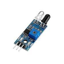
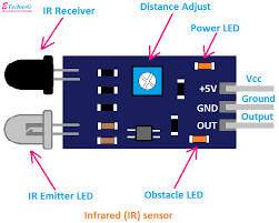
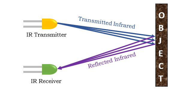
This IR Sensor consists of two parts, a Transmitter, and a Receiver. The transmitter emits IR light, and the object reflects that light. The photodiode (receiver) receives the reflected light. The amount of reflection and reception varies with distance. These differences cause a change in the input and thus used for proximity detection. IR LED sensor module has both the transmitter and emitter designed to work on the 940 nm wavelength.
A typical infrared detection system consists of five fundamental components: an infrared source, a transmission channel, an optical component, infrared detectors or receivers, and signal processing. Infrared sources include infrared lasers and infrared LEDs with specified wavelengths.
Vacuum, atmosphere, and optical fibers are the three basic types of media utilized for infrared transmission. Optical components are used to focus or limit the spectrum response of infrared radiation.
Specifications:
- The operating voltage is 5VDC
- I/O pins – 3.3V & 5V
- Mounting hole
- The range is up to 20 centimeters
- The supply current is 20mA
- The range of sensing is adjustable
- Fixed ambient light sensor
Types of Infrared Sensor
Infrared sensors are classified into two types like active IR sensor and passive IR sensor.
Active IR Sensor
The transmitter and receiver are both included in this active infrared sensor. The light-emitting diode is employed as a source in the majority of applications. A non-imaging infrared sensor is an LED, while an imaging infrared sensor is a laser diode.
These sensors operate on the basis of energy radiation, which is both received and detected. It can also be processed by utilising a signal processor to retrieve the relevant data. Reflectance and break beam sensors are the best examples of this active infrared sensor.
Passive IR Sensor
The passive infrared sensor consists only detectors and does not include a transmitter. These sensors make use of a transmitter or an infrared source. This object generates energy that infrared sensors detect. After that, a signal processor is utilised to decode the signal and extract the necessary data.
They are divided into two categories: quantum and thermal. Infrared radiation is used as a heat source in thermal infrared sensors. Thermal infrared detectors include thermocouples, pyroelectric detectors, and bolometers. Infrared sensors of the quantum kind have a better detection performance. It is faster than infrared detectors of the thermal kind. Quantum type detectors’ light sensitivity is wavelength dependant.
IR Sensor Working Principle
An infrared sensor works similarly as an object detection sensor does. This sensor contains an infrared LED and an infrared photodiode, which can be combined to make a photo-coupler or an optocoupler. Planks radiation, Stephan Boltzmann, and Weins displacement are the physics laws used in this sensor.
IR Transmitter or IR LED
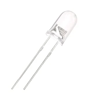
Infrared Transmitter is a light emitting diode (LED) which emits infrared radiations called as IR LED’s. Even though an IR LED looks like a normal LED, the radiation emitted by it is invisible to the human eye.
IR Receiver or Photodiode
IR Photodiode functions as an IR receiver used to detect the light rays reflected from an IR LED. The photodiode is basically a reverse-biased PN junction diode. When the photodiode is exposed to light, the electrical resistance across the diode decreases. Thereby increasing the reverse current. In case if the photodiode is not exposed to light, the resistance across the diode will be high. Hence the reverse current will be extremely small. This current is also known as a dark current.
There are various types of IR receivers based on wavelength, voltage, packaging, and other factors. The wavelength of the receiver should match that of the transmitter when utilised in an infrared transmitter – receiver combo.
These lights are not visible by naked eyes but can be seen through a camera. That is the reason why these IR sensors used in night vision cameras. When light falls on the IR sensor, the photodiode response in terms of change in resistance. This change in resistance measured in terms of voltage. This module can be connected directly to a microcontroller, Arduino, or Raspberry Pi with a few current limiting resistors.
IR Sensor Circuit Diagram
This IR Sensor circuit comprises the following components
- LM358 IC 2 IR transmitter and receiver pair
- Resistors of the range of kilo-ohms.
- Variable resistors.
- LED (Light Emitting Diode).
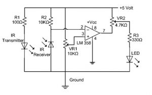
The transmitter part of this project includes an IR sensor that emits continuous IR rays that are received by an IR receiver module. The receiver’s IR output terminal changes depending on how well it receives IR photons. This output can be passed to a comparator circuit because this variation cannot be analysed separately. As a comparator circuit, an LM 339 operational amplifier (op-amp) is employed.
When the IR receiver does not receive a signal, the inverting input of the comparator IC has a higher potential than the comparator IC’s non-inverting input (LM339). As a result, the comparator’s output goes low, but the LED does not glows. The voltage at the inverting input goes low when the IR receiver module gets a signal. As a result, the comparator’s output (LM 339) turns high, and the LED begins to glow.
Resistor R1 (100 ), R2 (10k ), and R3 (330) are used to ensure that a minimum of 10 mA current passes through the IR LED Devices like Photodiode and normal LEDs respectively. Resistor VR2 (preset=5k ) is used to adjust the output terminals. Resistor VR1 (preset=10k ) is used to set the sensitivity of the circuit Diagram.
Advantages
- Low power consumption
- There is no data leakage because of the ray direction
- These sensors are not affected by oxidation & corrosion
- Noise immunity is strong
- Detects motion when the light is present or absent
- These sensors are not affected by rust
- They do not need to get in touch with objects for detection.
- No data leakage because of the directionality infrared radiation of ray
- These are more modest in size and are more moderate.
- It responds very quickly as compared to thermocouples.
- It provides high reliability
Disadvantages
- Line of sight is required
- Range is limited
- These can be affected by fog, rain, dust, etc
- Less data transmission rate
- These sensors can be blocked with common objects.
- High force IR signals can harm human eyes
IR Sensor Applications
IR sensors are classified into different types depending on the applications. IR sensors are used in a variety of projects and electronic devices. The following are some of them:
Radiation Thermometers

Radiation thermometers use infrared sensors to measure temperature, which is dependent on the object’s temperature and substance, and these thermometers contain some of the following qualities.
- Measurement without direct contact with the object
- Faster response
- Easy pattern measurements
Flame Monitors
These sensors are used to detect the light emitted by the flames and to keep track of how they’re burning. Flames emit light that ranges from ultraviolet to infrared. Some of the most widely utilized detectors in flame monitors are PBS, PbSe, two-color detectors, and pyroelectric detectors.
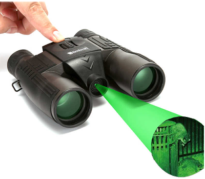
Night Vision Devices
An Infrared technology implemented in night vision equipment if there is not enough visible light available to see unaided. Night vision devices convert ambient photons of light into electrons and then amplify them using a chemical and electrical process before finally converting them back into visible light.
Gas Analyzers
IR sensors are used in gas analyzers that use the absorption characteristics of gases in the IR region. Two types of methods are used to measure the density of gas such as dispersive and nondispersive

IR Imaging Devices
The infrared image device is one of the most common uses of infrared photons, due to its invisibility. Thermal imagers, night vision equipment, and other accessories utilise it.
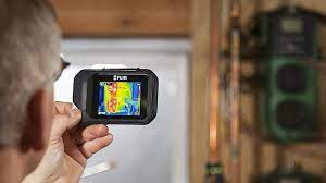
Water, rocks, soil, vegetation, and atmosphere, as well as human tissue, all emit infrared radiation. Thermal infrared detectors measure these IR radiations and map the object/spatial area’s temperature distributions on an image. Sb (indium antimonite), Gd Hg (mercury-doped germanium), and Hg Cd Te (mercury-cadmium-telluride) sensors are commonly used in thermal imagers.
Infrared Tracking
An Infrared tracking or Infrared homing, is a missile guidance system which operates using the infrared electromagnetic radiation emitted from a target to track it.
Other Key Application Areas:
- Climatology
- Meteorology
- Photo bio modulation
- Flame Monitors
- Gas detectors
- Water analysis
- Moisture Analyzers
- Anesthesiology testing
- Petroleum exploration
- Rail safety
- Gas Analyzers