
I am text block. Click edit button to change this text. Lorem ipsum dolor sit amet, consectetur adipiscing elit. Ut elit tellus, luctus nec ullamcorper mattis, pulvinar dapibus leo.
-33%
74LS132 Quadruple 2-Input Positive NAND Schmitt Trigger IC
Original price was: ₹22.50.₹15.00Current price is: ₹15.00. inc. GST

2.2uf 250V DC Polyester Capacitor
Original price was: ₹15.00.₹10.00Current price is: ₹10.00. inc. GST
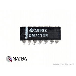
74LS13 Dual 4-Input Schmitt Trigger IC
Original price was: ₹30.00.₹20.00Current price is: ₹20.00. inc. GST
- 4-Input NAND gate Schmitt Trigger – Hex Inverter
- Operating Voltage: 5V
- Low Level Hysteresis voltage: 0.25V
- High Level Hysteresis voltage: 3.4V
- Output current High: -0.4mA
- Output current Low: 8.0mA
- Hysteresis voltage: 0.8V typically
- Typical Rise Time: 12nS
- Typical Fall Time: 12nS
- Available in 14-pin PDIP, GDIP, PDSO packages
Description
The 74LS13 is a Schmitt triggers hex 8-bit inverter IC with dual 4 inputs from the 74XXYY IC Series. The 74LS13 is a TTL (Transistor to Transistor Logic) device that employs low-power Shottky transistors to minimise stored charge and achieve faster switching rates than bipolar transistors. The IC 74LS13 operates with any TTL-based device and uses a single power source for all of the triggers.
The 74LS13 is a 4-input NAND gate Positive Dual Schmitt trigger, which means it has two Schmitt triggers, each with four inputs. The Schmitt trigger receives the final output after the four inputs have been processed by a NAND gate. To avoid the problem of hysteresis, a Schmitt trigger is utilised. It may also be used to smooth out a noisy signal and turn it into a crisp signal. We can convert a sinusoidal or triangular wave to a square wave using a schmitt trigger gate. If necessary, it can also be employed as a logic inverter. Additionally, a Schmitt trigger may be used to debounce many push buttons or other loud input devices.
A Schmitt Trigger is a comparator-based circuit that produces an output based on the output of the prior gate. The input value of a Schmitt Trigger might be analogue or digital, but the output is always in one of two forms: 1 or 0. Any circuit may be converted to Schmitt trigger by using a positive feedback scheme. The threshold utilised to get the output of a Schmitt Trigger circuit, on the other hand. The output remains HIGH when the value exceeds the threshold. It will be deemed in the LOW condition otherwise. Not only are these circuits used to convert analogue to digital, but they also assist reduce noise from the signal.
Reviews (0)
Shipping & Delivery

Related products

650NM Laser Diode
- Wavelength: 650nm
- Output optical power: 5mW
- Operating voltage: 5V
- Operating current: ~30mA
- Input current: 30mA
- Housing material: Copper
- Power lead length: 120mm.
- Transmit power: 58mW
- Spot: size 10mm to 15mm at 15meters
- Life span more than 2000 hours
- Driver circuit: APC circuit
- Small size
- Cost-effective
- Breadboard friendly
- Operating temperature -10°C to 40°C
- Dimension: :15mm x 6mm
- Weight: 10 grams

ADXL 335 Accelerometer IC
- 3-axis sensing
- Small, low profile package
- 4 mm × 4 mm × 1.45 mm LFCSP
- Low power : 350 μA (typical)
- Single-supply operation: 1.8 V to 3.6 V
- 10,000 g shock survival
- Excellent temperature stability
- BW adjustment with a single capacitor per axis
- RoHS/WEEE lead-free compliant
- 8V- 3.6V single-supply operation
- Integrated X, Y, and Z axis accelerometer on a single chip
- X and Y axis has a 0.5Hz to 1600Hz bandwidth
- Z axis has a 0.5Hz to 550Hz bandwidth
- Hermetically sealed for temp and humidity resistance


Dual Micro USB 3.7v to 5V 2A Power Bank DIY 18650 LiPo Charger
- 4-level LED lamp display power, not working state intelligent automatic shutdown;
- The built-in lithium battery protection IC, over-current, under-voltage protection;
- Dual USB output ports.
- Dimensions: 68 x 34 x 9 mm (LxWxH)
- Weight: 10 gm
- Input port: MicroUSB (Andro)
- Input requirements: 5V constant voltage power supply can do charge input power, the most matching charger for 5v1a above
- Output port: USB
- Output parameters: 5V1A/5V2A
- Requirements for rechargeable batteries:
- Compatible Batteries: 18650 batteries, cell phone batteries, flat-panel batteries, MP3 batteries, etc. 3.7v-4.2V polymer Lithium battery,
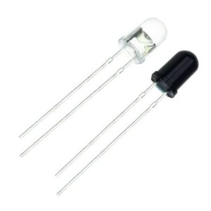
IR LED Sensor
- Size: 5mm LED
- Wavelength: 940nm wavelength (most commonly used)
- Forward current (IF) is 100mA (normal condition) and 300mA (max.)
- 5A of surge forward current
- 24v to 1.4v of forward voltage
- Temperature : -40 to 100 ℃
- Soldering Temperature should not exceed 260 ℃
- Power Dissipation of 150mW at 25℃ (free-air temperature) or below
- Spectral bandwidth of 45nm
- Viewing angle: 30 to 40 degree
- High Reliability
- Excessive radiant intensity
- Having lead spacing of 2.54mm
- Easy to use with breadboard or perf board


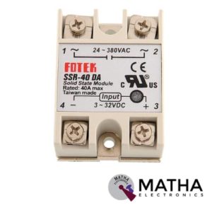
Solid State Relay Module DC To AC SSR-40DA 3-32VDC/24-380VAC 40A
- Control mode: DC-AC
- Input voltage: 3-32V DC.
- Output voltage: 24-380V AC.
- Output current: 40A.
- Working voltage: 250V.
- Material: plastic + metal.
- Loading current: 40A
- Control current: 3-25mA DC
- On voltage: ≤1.5V AC
- One-off Time: ≤10ms
- Off Leakage Current: ≤2mA
- Dielectrics voltage-resistance: 2500VAC
- Environment temperature: -30 to +75
- Long service life and high reliability.
- Reduced electromagnetic interference.
- Highly reliable, compact size designed to offer users maximum simplicity.
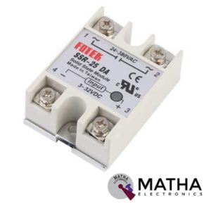
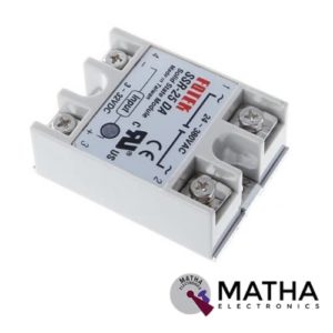
Solid State Relay Module SSR-25DA 25A /250V 3-32V DC Input 24-380VAC Output
- Control mode: DC-AC
- Input voltage: 3-32V DC.
- Output voltage: 24-380V AC.
- Output current: 25A.
- Working voltage: 250V.
- Material: plastic + metal.
- Environment temperature: -30 to +75
- Long service life and high reliability.
- Reduced electromagnetic interference.
- Highly reliable, compact size designed to offer users maximum simplicity.
- Dimension: 6. 5Cm x 4. 5Cm x 2. 2Cm
Reviews
There are no reviews yet.