
I am text block. Click edit button to change this text. Lorem ipsum dolor sit amet, consectetur adipiscing elit. Ut elit tellus, luctus nec ullamcorper mattis, pulvinar dapibus leo.
-8%

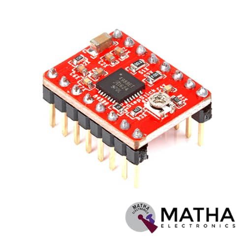
A4988 Stepper Motor
Original price was: ₹175.00.₹160.00Current price is: ₹160.00. inc. GST
DRV8825 Stepper Motor
Original price was: ₹300.00.₹275.00Current price is: ₹275.00. inc. GST
- Operating voltage: 8.2V to 45V
- Continuous current per phase: 1.5 Amp
- Maximum current per phase: 2.2 Amp
- Minimum logic voltage: 2.5V
- Maximum logic voltage: 5.25V
- Six different step resolutions: full-step, half-step, 1/4-step, 1/8-step, 1/16-step, and 1/32-step
- Compatible with 3V3 and 5V microcontrollers
- Our Board comes with 0.1 Ohm Sensor resistors
- The Correct current decay mode (fast decay or slow decay) selected by chopping control
- Over-temperature thermal shutdown, under-voltage lockout, and crossover-current protection
- Short-to-ground and shorted-load protection
- 4-layer, 2 oz copper PCB for improved heat dissipation
- Exposed solderable ground pad below the driver IC on the bottom of the PCB
- Dimensions : 15 x 20 mm.
- Weight: 4 gm.
Description
The DRV8825 stepper motor driver carrier designed as a breakout board based on TI’s DRV8825 micro-stepping bipolar stepper motor driver. It offers a wide range of advantages such as adjustable current limiting, over-temperature and over-current protection, and six microstep resolutions (down to 1/32-step). It operates at a wide operating voltage ranging from 8.2 – 45 V and can deliver up to approximately 1.5 A per phase without a heat sink or forced air flow (rated for up to 2.2 A per coil with sufficient additional cooling).
This module provides a nearly identical pinout and interface to those of the A4988 stepper motor drivers. As a result, used as a higher-performance drop-in replacement for many applications. DRV8825 stepper motor driver is easily controllable with any controller like Arduino, Raspberry Pi, AVR, and many others. Thus simplifies coding and ensures more flexibility in controlling motor.
DRV8825 stepper motor driver uses highly prominent Texas Instruments DRV8825 IC. This stepper motor can be controlled via just 2 pins. In which one for direction and the other for speed and step control. Thus makes it quite easy to control the speed and position of the motor from a microcontroller, Arduino, Raspberry Pi, etc. In case if we want to control a stepper Motor from Arduino, Raspberry Pi, or any other Micro-controller, this DRV8825 stepper motor driver will be a perfect choice. Thus simplify your coding and will give you more flexibility in controlling the stepper motor.
Application
- Printers and scanners
- 3D printers and CNC
- Roboticsufficient additional cooling).
Reviews (0)
Shipping & Delivery

Related products

A2212 BRUSHLESS DC MOTOR 2200KV
- Motor KV: 2200
- Operating voltage: 7.2V to 12V (2 to 3Li-poly or 6to10 NiCad)
- LiPO Batteries: 2S-3S
- No-load Current: 10 V: 0.5 A.
- Current Capacity: 12A/60S
- Maximum current:13Amp for 60Sec
- Maximum Watts:150 Watt
- Efficiency Current: 4-10A
- Shaft Diameter: 3.17 mm
- Prop Adapter is quality tested
- Minimum ESC Specification: 18A (30A Suggested)
- Maximum operating temperature: + 80°C
- Complete speed control because of three phase connection.
- Long life as there are no moving contact
- Thrust @ 3S with 1045 propeller: 1000gms approx.
- Thrust @ 3S with 0945 propeller: 750gms approx.
- Thrust @ 3S with 0845 propeller: 650gms approx.
- Motor Dimensions: 27.5 x 30mm
- Weight of motor:50-60 grams
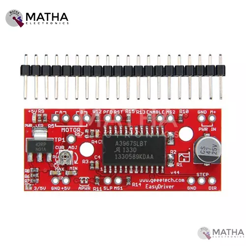
A3967 STEPPER MOTOR DRIVER
- A3967 precision micro-stepping driver
- Power supply: 7v to 30v
- Logic voltage: 5v to 3.3v
- Higher the voltage higher the torque at high speed
- Adjustable current control from 150Ma/ phase to 750ma phase
- Automatic current decay mode detection/selection
- Fast, slow, and mixed current decay modes
- Internal UVLO and thermal shutdown circuitry
- Crossover current protection
- Micro stepping resolution to full, half, quarter, and eighth steps by broken out MS1 and MS2 pins.
- Compatible with Arduino, GRBL G-Code interpreter for driving3-axis CNC machines
- Salington sink drivers used
- Compactible with 4, 6,8 wire stepper motor of any voltage

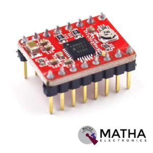
A4988 Stepper Motor
- Operating voltage supply: 8 V to 35 V
- Continuous current per phase: 1 Amp
- Maximum current per phase: 2 Amp
- Minimum logic voltage: 3V
- Maximum logic voltage: 5.5V
- Microstep resolutions: Full, 1/2, 1/4, 1/8, and 1/16
- Logic Voltage supply: 3.3 V to 5 V
- Compatible with 3V3 and 5V microcontrollers
- Our Board comes with 0.1 Ohm Sensor resistors
- Five different step resolutions: full-step, half-step, quarter-step, eighth-step, and sixteenth-step
- The Correct current decay mode (fast decay or slow decay) is selected by chopping the control
- Over-temperature thermal shutdown, under-voltage lockout, and crossover-current protection
- Short-to-ground and shorted-load protection
- 4-layer, 2 oz copper PCB for improved heat dissipation
- Exposed solderable ground pad below the driver IC on the bottom of the PCB

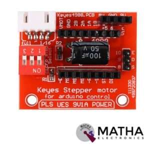
A4988 STEPPER MOTOR DRIVE CONTROLLER BOARD
- Operating voltage supply: 8 V to 35 V
- Continuous current per phase: 1 Amp
- Maximum current per phase: 2 Amp
- Minimum logic voltage: 3V
- Maximum logic voltage: 5.5V
- Microstep resolutions: Full, 1/2, 1/4, 1/8, and 1/16
- Compact size, easy to install and use.
- All jumpers hit the ON position to indicate 16 subdivisions (4988) or 32 subdivisions (8825).
- Jm connection motor; Jv Connects 5V and 12V-24V Power Supply.
- E /S /D /G of Jc corresponds to Enable /Step /Dir /Gnd driving signal output on the connection respectively.
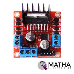

L298N MOTOR DRIVER
- Driver model: L298N 2A
- Driver chip: Double H bridge L298N
- Motor supply voltage: 46V(maximum)
- Motor supply current: 2A(maximum)
- Logic voltage: 5v
- Driver voltage: 5V-35V
- Driver current: 2A
- Logical current: 0-36mA
- Maximum power: 25W
- Current sensor for each motor
- LED indication for power status
- Heat sink for better performance
- Operating temperature: -25 degrees to 135 degrees Celsius
- Can be interfaced with simple manual switches, TTL logic gates, relays, etc.
- Dimension: 55*60*30mm
- Weight: 33gm


L298P Motor Shield motor driver
- L298P based Arduino motor driver shield
- Operating Voltage 5V to 12V
- Motor controller L298P, Drives 2 DC motors or 1 stepper motor
- The logical part of the input voltage VD: 5V
- Driven part of the input voltage VS: VIN Input 6.5 ~ 12V, PWRIN 4.8 ~ 35V input
- The logical part of the work current Iss:<36mA
- Driven part of the operating current Io:<2A
- Current sensing 1.65V/A
- Free running stop and brake function
- Maximum power dissipation: 25W (T = 75 Celsius)
- Max current 2A per channel or 4A max (with external power supply)
- Control signal input level: High 2.3V
- Onboard Bluetooth interface, you can directly plug, no wiring required.
- The board with L298P motor drive chip, directly with the motherboard digital I/O port (D10, D11, D12, D13), without cumbersome wiring.
- Onboard buzzer (D4), you can set the reverse alarm ringtones.
- D2, D3, D5, D6, D7, D9 are not occupied by the digital interface.
- A 0 – A 5 six analogue interfaces.
- Forward and Backward steering are indicators


MACH3 interface board
- Compatible Stepper Motor Driver - Max 5 2-phase Microstep controllers
- Driver type - Pulse and Direction signal control
- Wide input voltage range: 12-24V, and with anti-reverse function.
- Output 0-10V analogue voltage for the inverter to control the spindle speed.
- Compatible with MACH3, Linux CNC (EMC2) etc. parallel-control CNC software.
- USB power supply and peripherals power phase are separate to protect computer security.
- All the signals are to-isolate which can protect your computer security.
- 5-input interface to define the Limit, Emergence-Stop, Cutter alignment, etc.
- Wide input voltage range: 12-24V, and with anti-reverse function.
- One relay output control interface, accessed by the spindle motor or the air pump, water pump, etc.
- Maximum support 5-axis stepper motor driver controllers
- Output 0-10V analogue voltage for the inverter to control the spindle speed.
- All the way to the relay output port, control spindle switch. Output port P17 mouth.
- One relay output control interface, accessed by the spindle motor or the air pump, water pump, etc.
- Weight - Approx. 75g
- Dimensions - 90 * 70 * 20mm
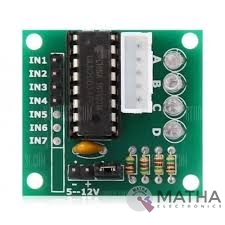
ULN2003 Driver
- Contains 7 high-voltage and high current Darlington pairs
- Each pair is rated for 50V and 500mA
- Input pins can be triggered by +5V
- All seven Output pins can be connected to gather to drive loads up to (7×500mA) ~3.5A.
- Can be directly controlled by logic devices like Digital Gates PIC etc
- Available in 16-pin DIP, TSSOP, SOIC packages
- Dimensions: 32 x 18 x 11mm (LxWxH)
- Weight: 3 gm
Reviews
There are no reviews yet.