
I am text block. Click edit button to change this text. Lorem ipsum dolor sit amet, consectetur adipiscing elit. Ut elit tellus, luctus nec ullamcorper mattis, pulvinar dapibus leo.
-8%

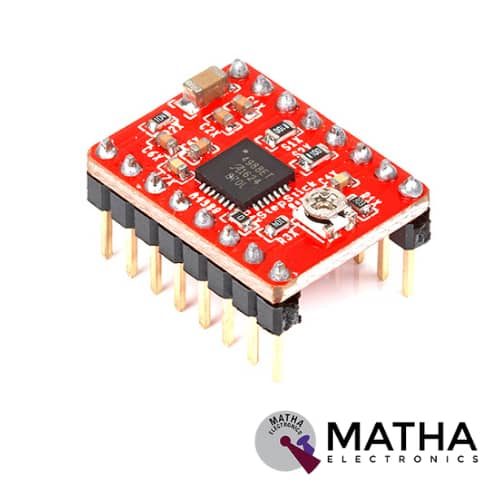
A4988 Stepper Motor
Original price was: ₹175.00.₹160.00Current price is: ₹160.00. inc. GST
DRV8825 Stepper Motor
Original price was: ₹300.00.₹275.00Current price is: ₹275.00. inc. GST
- Operating voltage: 8.2V to 45V
- Continuous current per phase: 1.5 Amp
- Maximum current per phase: 2.2 Amp
- Minimum logic voltage: 2.5V
- Maximum logic voltage: 5.25V
- Six different step resolutions: full-step, half-step, 1/4-step, 1/8-step, 1/16-step, and 1/32-step
- Compatible with 3V3 and 5V microcontrollers
- Our Board comes with 0.1 Ohm Sensor resistors
- The Correct current decay mode (fast decay or slow decay) selected by chopping control
- Over-temperature thermal shutdown, under-voltage lockout, and crossover-current protection
- Short-to-ground and shorted-load protection
- 4-layer, 2 oz copper PCB for improved heat dissipation
- Exposed solderable ground pad below the driver IC on the bottom of the PCB
- Dimensions : 15 x 20 mm.
- Weight: 4 gm.
Description
The DRV8825 stepper motor driver carrier designed as a breakout board based on TI’s DRV8825 micro-stepping bipolar stepper motor driver. It offers a wide range of advantages such as adjustable current limiting, over-temperature and over-current protection, and six microstep resolutions (down to 1/32-step). It operates at a wide operating voltage ranging from 8.2 – 45 V and can deliver up to approximately 1.5 A per phase without a heat sink or forced air flow (rated for up to 2.2 A per coil with sufficient additional cooling).
This module provides a nearly identical pinout and interface to those of the A4988 stepper motor drivers. As a result, used as a higher-performance drop-in replacement for many applications. DRV8825 stepper motor driver is easily controllable with any controller like Arduino, Raspberry Pi, AVR, and many others. Thus simplifies coding and ensures more flexibility in controlling motor.
DRV8825 stepper motor driver uses highly prominent Texas Instruments DRV8825 IC. This stepper motor can be controlled via just 2 pins. In which one for direction and the other for speed and step control. Thus makes it quite easy to control the speed and position of the motor from a microcontroller, Arduino, Raspberry Pi, etc. In case if we want to control a stepper Motor from Arduino, Raspberry Pi, or any other Micro-controller, this DRV8825 stepper motor driver will be a perfect choice. Thus simplify your coding and will give you more flexibility in controlling the stepper motor.
Application
- Printers and scanners
- 3D printers and CNC
- Roboticsufficient additional cooling).
Reviews (0)
Shipping & Delivery

Related products

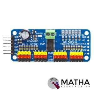
16-Channel 12-bit PWM/Servo Driver I2C interface PCA9685 for Arduino Raspberry Pi
- Adjustable frequency PWM up to about 1.6 kHz
- 12-bit resolution for each output – for servos, that means about 4us resolution at a 60Hz update rate
- Configurable push-pull or an open-drain output
- The output enable pin to quickly disable all the outputs
- Terminal block for power input
- Reverse polarity protection on the terminal block input
- Green power-good LED
- 3 pin connectors in groups of 4 so you can plug in 16 servos at once
- Chainable design
- A spot to place a big capacitor on the V+ line
- 220-ohm series resistors on all the output lines to protect them, and to make driving LEDs trivial.
- This board/chip uses an I2C 7-bit address between 0x60-0x80, selectable with jumpers.

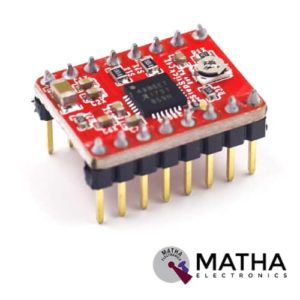
A4988 Stepper Motor
- Operating voltage supply: 8 V to 35 V
- Continuous current per phase: 1 Amp
- Maximum current per phase: 2 Amp
- Minimum logic voltage: 3V
- Maximum logic voltage: 5.5V
- Microstep resolutions: Full, 1/2, 1/4, 1/8, and 1/16
- Logic Voltage supply: 3.3 V to 5 V
- Compatible with 3V3 and 5V microcontrollers
- Our Board comes with 0.1 Ohm Sensor resistors
- Five different step resolutions: full-step, half-step, quarter-step, eighth-step, and sixteenth-step
- The Correct current decay mode (fast decay or slow decay) is selected by chopping the control
- Over-temperature thermal shutdown, under-voltage lockout, and crossover-current protection
- Short-to-ground and shorted-load protection
- 4-layer, 2 oz copper PCB for improved heat dissipation
- Exposed solderable ground pad below the driver IC on the bottom of the PCB


DM556 Digital Stepper Motor Driver with Micro Stepping 20 to 50V 5.6A
- Good high-speed performance
- Supply voltage: +50VDC
- Output current from 0.5A to 5.6A
- Pulse input frequency up to 200 kHz
- Extremely cost-effective
- Automatic idle-current reduction
- Self-test and Auto-configuration technology TTL compatible and optically isolated input
- Micro step resolutions programmable, from full-step to 102,400 steps/rev
- Suitable for 2-phase and 4-phase motors
- Support PUL/DIR and CW/CCW modes
- Anti-Resonance provides optimum torque and nulls mid-range instability
- Extra-low motor noise offers excellent quietness
- Over-voltage, over-current protection and phase error protection


L293D Motor Driver Shield
- L293D motor driver chip & 74HC595 shift register
- Four H-bridges
- Terminal blocks and jumper to connect external power, for separate logic/motor supplies
- Up to 4 bi-directional DC motors with individual 8-bit speed selection
- Up to 2 stepper motors (unipolar or bipolar) with single coil, double coil or interleaved stepping.
- 2 connections for 5V ‘hobby’ servos connected to the Arduino’s high-resolution dedicated timer
- 4 H-Bridges: L293D chipset provides 0.6A per bridge (1.2A peak) with thermal shutdown protection, internal kickback protection diodes. Can run motors on 4.5VDC to 25VDC.
- Pull-down resistors keep motors disabled during power-up
- Big terminal block connectors to easily hook up wires (18-26AWG) and power
- Arduino reset button brought up top
- Tested compatible with Arduino Mega 1280 & 2560, Diecimila, Duemilanove, and UNO
- PCB Size: 69 x 53 mm
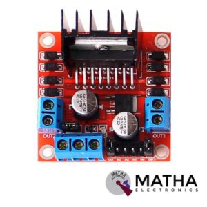

L298N MOTOR DRIVER
- Driver model: L298N 2A
- Driver chip: Double H bridge L298N
- Motor supply voltage: 46V(maximum)
- Motor supply current: 2A(maximum)
- Logic voltage: 5v
- Driver voltage: 5V-35V
- Driver current: 2A
- Logical current: 0-36mA
- Maximum power: 25W
- Current sensor for each motor
- LED indication for power status
- Heat sink for better performance
- Operating temperature: -25 degrees to 135 degrees Celsius
- Can be interfaced with simple manual switches, TTL logic gates, relays, etc.
- Dimension: 55*60*30mm
- Weight: 33gm

Leadshine DM320C
- Supply voltage up to +30 VDC
- Output current programmable, from 0.3A to 2.0A
- Pulse input frequency up to 70 kHz
- TTL compatible and optically isolated input
- Automatic idle-current reduction
- Suitable for 2-phase and 4-phase motors
- Support PUL/DIR and CW/CCW modes
- Over-voltage, over-current, phase-error protection
- Anti-Resonance provides optimum torque and nulls mid-range instability
- Self-test and Auto-configuration technology offers optimum responses with different motors
- Microstep resolutions programmable, from full-step to 102,400 steps/rev
- Support PUL/DIR and CW/CCW modes
- Over-voltage, over-current, phase-error protection
- Its unique features make the DM320C an ideal solution for applications that require low-speed smoothness


Reviews
There are no reviews yet.