
What is PWM: Pulse Width Modulation? Its Advantages and Disadvantages
Let’s begin by learning what pulse is. One of the most fundamental concepts in basic electronics is this. There are two possible output states in digital systems: digital high, or “1,” and digital low, or “0.” A continuous signal called a pulse has a succession of these 1s and 0s. An example of a digital pulse with logic 1 or high logic at 3V and logic 0 or low logic at 0.2V is shown in the image below. Since this alternate logic pattern repeats over time, it qualifies as a digital pulse signal.
What is PWM or Pulse Width Modulation?
Modulation is the process of altering or modifying a signal using another signal in order to create a stronger signal. This is a very prevalent practice in transmission systems to allow for audio signal delivery.
Similar to this, PWM refers to modulating a digital signal’s pulse using another signal, most frequently an analog signal.
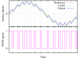
The modulated signal’s outcome will have altered width in all of its logical states, as seen in the graphic above. You can notice in the following graphic that the width of the high state varies depending on the logic 1 you apply. In essence, this indicates that the length of time between each logic high varies, as shown by the changed width pulse signal above.
Why do we need PWM?
PWM signals play a big part in power PCBs, driving circuits, and other things. when a gadget is powered by a PWM signal as opposed to a constant DC supply. Using PWM, we will be able to regulate the length of time current really flows through the device because the ON and OFF states are variable.
When the pulse is in ON state current will be delivered to the device, when signal is in OFF state current will no flow through. When the pulse frequency is high enough, the device won’t experience any power interruptions at all and will continue to run normally while using less electricity. Below, this is further discussed.
Duty Cycle of PWM
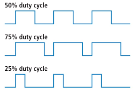
The percentage of cycles in which a time-high condition is displayed is known as the duty cycle. The average current can be calculated from a PWM signal using the duty cycle; the output is derived by averaging the ON and OFF times.
Consider a device that is powered by a PWM signal with a duty cycle of 50% and equal time for the high and low states. Now, we can state that the device’s current consumption will be halved when driven by a DC signal and that its duty cycle will be set at 25%. When compared to a conventional DC signal, a PWM signal provides a 3/4 current at a duty cycle of 75%.
Advantages of pulse width modulation :
- Cheap to make
- Low power consumption
- Efficiency up to 90 %
- A signal can be separated very easily at demodulation and noise can be also separated easily
- High power handling capacity
- Can utilize very high frequency
- Little heat whilst working
- Noise interference is less
- Very energy efficient when used to convert the voltage or to his light bulb
- A system in moderate inefficiency among all three types
- Synchronization between transmitter and receiver is not required unlike pulse position modulation (PPM)
- Filter requirement is reduced
- Amplitude and frequency can be control independently
- Significance reduction in THD of load current
Disadvantages of pulse width modulation :
- The complexity of the circuit
- Voltage spikes
- The system requires a semiconductor device with low turn ON and turn OFF times. Hence they are very expensive
- Radiofrequency interference
- Electromagnetic noise
- Bandwidth should be large to use in communication
- High switching loss due to the high PWM frequency
- Instantaneous power of the transmitter is varies