
Raspberry Pi Pico-A Complete Guide
The Raspberry Pi Foundation has released the Raspberry Pi PICO, their first dual-core ARM Cortex M0+ processor-based smallest-sized [to date] and budget-friendly Single Board Computer.

Raspberry Pi Pico is a brand new interesting Microcontroller board based on the Raspberry Pi Foundation’s RP2040 Microcontroller. The Raspberry Pi Pico is an inexpensive Arm-based microcontroller that can be programmed in C/C++ and MicroPython.
Introduction to Raspberry Pi Pico
Raspberry Pi PICO is a new device produced by the Raspberry Pi Foundation that is significantly less expensive than existing Raspberry Pi products. Raspberry Pi PICO is a Single Board Computer (SBC) with the smallest size development board, and it includes an RP2040 Microcontroller chip made by the Raspberry Pi Foundation. The Raspberry Pi Pico breakout board is specifically built for the RP2040. It resembles other microcontroller boards in appearance, with the MCU in the centre, a micro-USB connector on one end, and a row of contacts on each side. At the opposite end of the board, there is a 3-pin debug connection.
It combines the RP2040 with 2MB of Flash memory and a power supply chip that accepts input voltages ranging from 1.8 to 5.5V. This enables Pico to be powered from a wide range of sources. This comprises two or three AA cells connected in series, as well as a single lithium-ion cell.

The Raspberry Pi Pico is 51 by 21 mm in size, which is the same as an ESP32 Pico Kit and somewhat larger than an Arduino Nano or Micro. The Pico has 2 MB of QSPI Flash memory and 25 of the RP2040’s 30 GPIO pins have been extended out on extension connections. The board is breadboard compatible and will fit flawlessly on a breadboard.

Features of Raspberry Pi Pico:
- Operating Voltage: 1.8-5.5 VDC
- Processor: RP2040 (Dual-core Arm Cortex M0+) By Raspberry Pi
- RAM: 264 KB
- GPIO: 26 Pins
- Clock Speed: 133 MHz
- On-Board Port: Micro-USB 5V/2.5A DC Power Input Port
- 2MB of onboard Flash memory
- The castellated module allows soldering directly to carrier boards
- USB 1.1 with device and host support
- Low-power sleep and dormant modes
- Drag-and-drop programming using mass storage over USB
- 26 multi-function GPIO pins
- 2 SPI, 2 I2C, 2 UART, 3 12-bit ADC, 16 controllable PWM channels
- Accurate clock and timer on-chip
- Operating Temperature Range: -20 to 85 degrees C
- Temperature sensor
- Accelerated floating-point libraries on-chip
- 8 Programmable I/O (PIO) state machines for custom peripheral support
RP2040 – A Microcontroller By Raspberry Pi Pico

The Raspberry Pi Pico is a low-cost microcontroller board with flexible digital interfaces. It includes the RP2040, which is Raspberry Pi’s first in-house microprocessor. Pico supports the RP2040 chip with minimum (but flexible) additional circuitry.Although the Pico only has 4MB of off-chip Flash memory, the RP2040 is capable of supporting up to 16MB.
The user IO pins on the left and right edges of the board get the majority of the RP2040 microcontroller pins. Internally, four RP2040 IO are utilised to drive an LED, regulate the on-board Switched Mode Power Supply (SMPS), and sense the system voltages.
Specifications:
- Dual-core 32-bit ARM Cortex-M0+
- Runs at 48MHz, but can be overclocked to 133MHz
- 30 GPIO pins (26 exposed)
- Can support USB Host or Device mode
- 8 Programmable I/O (PIO) state machines
The Raspberry Pi Pico RP2040 controller is compatible with both c/c++ and micro-python, so if you’re a novice looking to learn one of these languages, the Raspberry Pi Pico is the perfect place to start.
Raspberry Pi Pico Pinout
This is a top view of the pinouts on the Raspberry Pi Pico. The pin labels are on the bottom of the board.
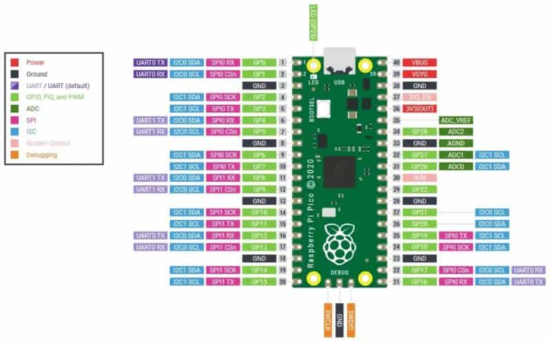
The Raspberry Pi Pico has 40 pins. 26 of the 40 pins are Input-Output (I/O) (IO Pins). All 14 of the pins are analogue, digital, and serial pins. There are 14 power and system-related pins on the board. The final three pins are utilised for SWD debugging. I2C0 and I2C1 are the two available I2C peripherals. Similarly, two SPI peripherals, SPI0 and SPI1, are available. There are also two UART Pins, UART0 and UART1. You can assign any of these to any of the available pins. You must solder 40 pin male headers, 20 on each side of the board, before you can use the Raspberry Pi Pico.
Raspberry Pi Pico Board-In Detail

- The microUSB port on one end of the board is the most prominent feature. This serves as a communications hub as well as a power source for the Pico.
- Next to the microUSB port is an on-board LED that is internally connected to GPIO pin 25. The fact that this is the lone LED on the entire Pico board is worth noting.
- The BOOTSEL pushbutton switch, located just below the LED, allows you to alter the Pico’s boot mode, allowing you to install MicroPython and conduct drag-and-drop programming.
- Three connections at the bottom of the board are for a serial Debug option that we won’t be looking at today, but that advanced developers may be interested in.
- The RP2040 MCU, which we’ll look at in a minute, sits in the centre of the board and serves as the brains of the system.
Ground Pins
- On the board, there are eight ground connections, plus one on the 3-pin Debug connector.
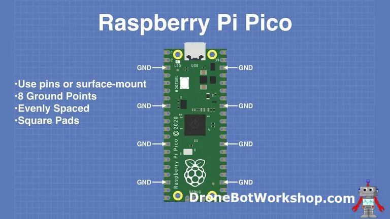
- These pins are easier to recognise since they are evenly spaced and square rather than rounded like the others.
- On pin 33, one of the ground connections is likewise labelled Analog Ground.
Power Pins
- The Pico is a 3.3-volt logic device, but with to a built-in voltage converter and regulator, it can be supplied with a variety of power supply.

All of the power-related pins are grouped together near the microUSB connector on the board.
- VBUS — This is the 5-volt power supply from the microUSB bus. There will be no output here if the Pico is not powered by the microUSB port.
- VSYS is the input voltage, which can be anywhere between 2 and 5 volts. The Pico’s on-board voltage converter will convert it to 3.3 volts.
- 3V3 — The Pico’s inbuilt regulator produces a 3.3-volt output. It can be used to power additional components as long as the load is less than 300ma.
There are a couple of inputs that can be used to control the Pico’s power.
- 3V3 EN — Disable the Pico’s internal voltage regulator with this input, which will turn off the Pico and any components powered by it.
- RUN – This line can be used to turn on or off the RP2040 microcontroller, as well as to reset it.
GPIO Pins
On the Raspberry Pi Pico board, there are 26 GPIO connections that are visible. They’re organised rather nicely, with a “gap” between GPIO 22 and GPIO 26 (the “missing” pins are used internally). Almost all of these pins have several uses, and up to 16 of them can be configured for PWM. Two I2C buses, two UARTs, and two SPI buses are available, each of which can be configured to use a wide range of GPIO pins.

Analog Pins
Three Analog-to-Digital Converters are included in the Pico, with a fourth being used internally for an on-board temperature sensor.The ADCs have a resolution of 12 bits. On the ADC VREF pin, you can additionally provide an external precise voltage-reference. For that reference, one of the grounds, the ADC GND on pin 33, is used as a ground point.

Programming Raspberry Pi Pico:
The Pi Pico may be programmed in a variety of languages, including C/C++ and Python.
- MicroPython – A subset of Python, MicroPython is an interpreted language that is made specifically for microcontrollers.
- C++ – Many microcontroller users have familiarity with C++ as it is used on the Arduino and ESP32 boards.
Pico may be used for a wide variety of applications and skill levels, and getting started is as simple as dragging and dropping a file. If you are working with C, it is best to utilise a Linux-based system, such as a Raspberry Pi Computer, since it is simple to get the SDK and build C programmes in Linux.
However, I recommend that you programme the Raspberry Pi Pico Board with MicroPython. To program the Raspberry Pi Pico using Micropython, you can either use:
MicroPython on Raspberry Pi Pico
MicroPython is a microcontroller-friendly version of Python 3. Damien George designed it, and it was originally used with the PyBoard development board in 2014. Since then, more devices have adopted this simple language, and Adafruit has released CircuitPython, a clone of MicroPython that provides more features for their range of boards. The Thonny Python IDE, which is available for all major OSes and is the most accessible method to get started with your Pico, may be used to write MicroPython code for the Raspberry Pi Pico.
CircuitPython, a clone of MicroPython, has been released for RP2040 boards. CircuitPython, developed by Adafruit, contains a large library of pre-written modules for sensors, LCD / OLED / LED screens, and output devices like thermal printers. CircuitPython is as easy to install on the Raspberry Pi Pico as MicroPython, and it’s reversible if you want to go back to MicroPython or C/C++.
C/C++ on Raspberry Pi Pico
There are two approaches for writing code in C/C++. We can first write the code in any text editor we like, then follow a workflow to create the files that are then flashed to the Pico. Alternatively, we can employ a graphical approach and have Microsoft’s Visual Studio Code manage the creation, build, and flashing processes all in one app.
How To Power Raspberry Pi Pico Board?
The following are the two methods for powering a Raspberry Pi Pico Board.
1) Using a USB port to power the latest Pico board
2) Powering the Raspberry Pi Pico with the VBUS and VSYS pins.
Powering The Raspberry Pi Pico Through USB Port
This is the most straightforward way to supply power to a Raspberry Pi Pico microprocessor. When we attach the USB connection to the board, the VSYS and therefore the system will be powered by a 5v USB VBUS voltage.
However, as I previously stated, this technique of powering the Raspberry Pi Pico board is a little tricky, and a little mistake could result in the device being damaged. As a result, when utilising this way of powering the Raspberry Pi Pico board, you must be more cautious.
Powering The Raspberry Pi Pico board through VBUS And VSYS Pins
Li-ion cells and a P-channel Mosfet can be used to power the latest Raspberry Pi Pico board in the second option. Please see the graphic below for further information on how to power the newest Raspberry Pi Pico board using Li-ion batteries.

Here, we have connected the gate terminal of the P-channel to the VBUS pin. When we attach the USB cord to the Raspberry Pi Pico board, this configuration will immediately turn off the second power source. If you want to learn more about how this design disconnects the second power source, check the article “P-channel Mosfet as a Switch.”
Conclusion
The Raspberry Pi Pico is a low-cost microcontroller board with flexible digital interfaces. It includes the RP2040, which is Raspberry Pi’s first in-house microprocessor. The Raspberry Pi Pico is a well-rounded product that includes the best aspects of its competitors, such as the Teensy and the ESP series. It also offers good documentation and community support, in keeping with Raspberry Pi history.
You’ll be curious to learn more about this new microcontroller now that you’ve seen how fantastic the Raspberry Pi Pico board is.Hope you all find this article useful.