
How to design a Simple 1 Watt Mono Audio Amplifier?
Here we are designing a simple mono audio amplifier project with a single IC KIA6278P. IC1 has eight pins. This mono audio amplifier will provide 1 Watt of output power with a 6 Volt power source and a 4 Ohm loudspeaker. The IC1 KA6278P is readily available for purchase and is inexpensive.
Components Required
Semiconductor:
- IC1: KIA6278P (8-pins)
Electrolytic capacitor:
- C3:100uF/25V
- C4:47uF/25V
- C5:100uF/25V
- C6:470uF/25V
Ceramic capacitor:
- C1: 104
- C2: .04uF
Miscellaneous:
- 8-pin IC socket
- 5cm*6.5cm Veroboard
- Two 2-pin Connectors
- Colour wires, a small metal screwdriver, and 4*1.5 Volts battery, signal generator e.t.c.
Circuit and working
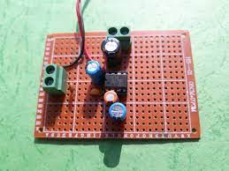
The prototype of this amplifier is shown in the figure.
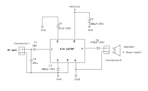
- Pin 1 of IC1 (KIA 6278P) is connected to an input terminal via a ceramic capacitor C1, as indicated in the circuit diagram (104). A 0.04uF capacitor is linked to an input terminal and ground. A noise signal present in the audio input stream will be filtered by capacitor C2.
- The positive (+) end of the electrolytic capacitor C3 (100uF/25V) is connected to pin 3 and the ground, while the negative terminal is connected to the ground.
- The positive terminal (+) of another electrolytic capacitor C4 (47uF/25V) is connected to pin 2 of IC1 while the negative terminal is connected to the ground.
- The fifth and sixth pins are grounded. A 2-pin connector connects Pin 7 to the electrolytic capacitor C6 (470uF/25V) and a 1 Watt/4 Ohms speaker.
- IC1’s pin 8 is wired to + 6V DC. A 100uF/25V electrolytic capacitor is connected to pin 8 of IC1 and ground. A DC voltage will be filtered by capacitor C5.
Construction and testing
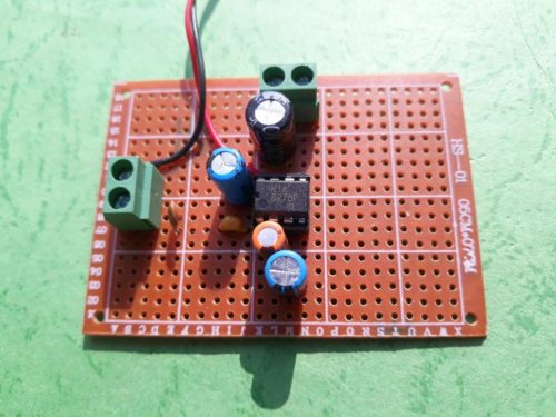
- This amplifier can be assembled on a 5cm*6.5cm Veroboard or a circuit board provided in the article.
- In the center of a 5cm*6.5cm veroboard, place an 8-pin IC socket.
- Utilizing a low wattage soldering iron, carefully solder an 8-pin IC socket onto a Veroboard.
- Solder two 2-pin connectors to the right and left sides of the Veroboard. Place all ceramic capacitors C1, C2, and electrolytic capacitors C3, C4, C5, and C6 on your Veroboard as depicted in the schematic.
- Connect a 1 Watt/4 Ohms speaker to a two-pin connector after completing the circuit assembly.
- Connect an AC/DC power supply or 4*1.5 V battery with a voltage of 6 volts to your amplifier.
Calibration and adjusting
Signal generators can be used for calibration and adjustment. If you lack a signal generator, you may test with a little metal screwdriver.
Connect a power source to your circuit. Take the screwdriver and lightly touch an AF input terminal (connector2). A humming sound should emanate from a speaker. Now link the audio source’s input (MP3 player, computer, mobile, laptop e.t.c.). Enjoy music listening.
Conclusion
Hope this blog helps you to understand how to design a Simple 1 Watt Mono Audio Amplifier. We, MATHA ELECTRONICS will come back with more informative blogs.