
So, in this project, I’ll show you how to make an Arduino temperature-controlled fan using a DHT11 sensor. To obtain the temperature value, we will utilize the DHT11 sensor, which will be printed on the LCD.
WHAT IS A TEMPERATURE-CONTROLLED FAN?
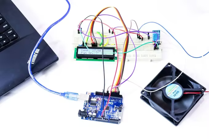
At the present, the fans which are used in homes can be switched on or off manually and the speed of these ceiling fans is also controlled by using a speed regulator. But now, as technology is developing day by day, everyone is looking toward smarter and automated technologies. Here, in our proposed system microcontroller Arduino UNO is used to control and automate processes. As a result, we’ll be able to adjust the fan speed in our home or anywhere else based on the current room temperature, as well as see the temperature and fan speed changes on a 16×2 LCD display.
This project is based on pulse width modulation for controlling the speed of the Brushless DC fan and also displaying the speed of the fan. The DHT11 temperature sensor is used to monitor the current temperature in the room and is display the value via 16×2 LCD. In order to operate the Brushless DC fan we required 25KHZ frequency and also install the PWM library to achieve that amount of frequency.
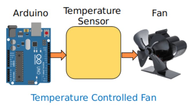
The output of the sensor is obtained, and the temperature value is converted to a suitable number on the Celsius scale. PWM signals are used to control the fan speed. Then we coded our Arduino to meet the specifications. It’s quite simple to work on this. We used Arduino to generate PWM and connected it to the transistor’s base terminal. Following that, the transistor generates a voltage in response to the PWM input
COMPONENTS REQUIRED:

- Arduino UNO
- USB A to B
- Breadboard
- DHT11 sensor
- DC Fan
- 2n2222 transistor
- 16×2 LCD
- Connecting wires
Arduino UNO
Arduino Uno is an open-source based on the Microchip ATmega328P developed by Arduino. cc. The current version of Arduino Uno comes with a USB interface, 14 digital I/O pins, 6 analog pins, an ICSP header, 16 MHz ceramic resonators, a power jack, and a reset button. And an Atmega328 microcontroller is used to connect with external electronics circuits.

DHT11 sensor
DHT11 is a low-powered electronic device that lets us get the value of the temperature and the moisture and it uses 1 wire protocol. The sensor consists of a capacitive humidity sensor and a Thermistor connected to a high-performance 8-bit microcontroller. It measures the surrounding air and outputs a digital signal on the data pin (no analog input pins are needed).DHT11 is strictly factory calibrated that is extremely accurate on humidity calibration, hence easy to interface with other microcontrollers. Using dedicated digital module acquisition technology and temperature, and humidity sensors ensures the products with high reliability and excellent long-term stability.

2n2222 transistor
This 2N2222A NPN bipolar transistor is specifically intended for use in low-power silicon NPN bipolar junction transistors. The 2N2222A has a very low saturation voltage and excellent high gain performance. Within the operating range, the 2N2222A is a three-terminal NPN device. The current through another pair of terminals is controlled by a voltage or current provided to one pair of transistor terminals. A transistor can magnify a signal because the regulated (output) power can be higher than the controlling (input) power.

16×2 LCD
Displaying information is one of the crucial steps in electronic projects. So using LCDs has always been one of the most popular ways to display information. This 1602 LCD module is a very popular display. 16*2 LCD module consists of 16 columns and 2 rows, so it has 32 (16*2) characters in total.

CONNECTIONS:
- LCD connection with Arduino
LCD is directly connected to Arduino (Check this tutorial for more details: LCD Interfacing with Arduino Uno). Connect pins of LCD- RS, EN, D4, D5, D6, and D7 to Arduino’s digital pin numbers 7, 6, 5, 4, 3, and 2.

- DHT 11 temperature and humidity sensor connection
A DHT11 sensor module is also attached to Arduino’s digital pin 12. Through the transistor, digital pin 9 is used to control fan speed.

- Upload the code
The code is in the part below. The first table illustrates what PWM value will determine the fan’s speed. You can alter the values to suit your needs.
Code:

PROGRAM CODE:
| #include “DHT.h” #include<LiquidCrystal.h> LiquidCrystal lcd(7, 6, 5, 4, 3, 2); #define DHTPIN 12 // what pin we’re connected to #define DHTTYPE DHT11 // DHT 11 #define pwm 9 byte degree[8] = { 0b00011, 0b00011, 0b00000, 0b00000, 0b00000, 0b00000, 0b00000, 0b00000 }; // Initialize DHT sensor for normal 16mhz Arduino DHT dht(DHTPIN, DHTTYPE); void setup() { lcd.begin(16, 2); lcd.createChar(1, degree); lcd.clear(); lcd.print(” Fan Speed “); lcd.setCursor(0,1); lcd.print(” Controlling “); delay(2000); analogWrite(pwm, 255); lcd.clear(); lcd.print(“Robu “); delay(2000); Serial.begin(9600); dht.begin(); } void loop() { // Wait a few seconds between measurements. delay(2000); // Reading temperature or humidity takes about 250 milliseconds! // Sensor readings may also be up to 2 seconds ‘old’ (its a very slow sensor) float h = dht.readHumidity(); // Read temperature as Celsius float t = dht.readTemperature(); // Read temperature as Fahrenheit float f = dht.readTemperature(true); // Check if any reads failed and exit early (to try again). if (isnan(h) || isnan(t) || isnan(f)) { Serial.println(“Failed to read from DHT sensor!”); return; } // Compute heat index // Must send in t in Fahrenheit! float hi = dht.computeHeatIndex(f, h); Serial.print(“Humidity: “); Serial.print(h); Serial.print(” %\t”); Serial.print(“temperature: “); Serial.print(t); Serial.print(” *C “); Serial.print(f); Serial.print(” *F\t”); Serial.print(“Heat index: “); Serial.print(hi); Serial.println(” *F”); lcd.setCursor(0,0); lcd.print(“temp: “); lcd.print(t); // Printing terature on LCD lcd.print(” C”); lcd.setCursor(0,1); if(t <20 ) { analogWrite(9,0); lcd.print(“Fan OFF “); delay(100); } else if(t==26) { analogWrite(pwm, 51); lcd.print(“Fan Speed: 20% “); delay(100); } else if(t==20) { analogWrite(pwm, 102); lcd.print(“Fan Speed: 40% “); delay(100); } else if(t==28) { analogWrite(pwm, 153); lcd.print(“Fan Speed: 60% “); delay(100); } else if(t==29) { analogWrite(pwm, 204); lcd.print(“Fan Speed: 80% “); delay(100); } else if(t>29) { analogWrite(pwm, 255); lcd.print(“Fan Speed: 100% “); delay(100); } delay(3000); } |
CONCLUSION:
Our proposed system-Temperature Controlled Fan using Arduino system has been designed and executed successfully. The output of the system was checked by setting the temperature at different levels and it was recorded that the fan speed changes accordingly. This device is a perfect choice for handicapped people. This proposed circuit can be used not only in fans but also in many practical applications, where the circuit can be connected to a device whose temperature has to be controlled at a particular value. Moreover, this designed circuit helps in preventing the waste of energy when it is not hot enough to use a fan and assists the disabled to switch on or off the fan automatically.