
What is Arduino Mega 2560?
Nowadays the electronic devices are becoming compact, flexible, and cheap that are capable of doing more function as compared to their predecessors. A Microcontroller was introduced as a new innovation in the electronics industry. Designed with the purpose of making our tasks easier, with minimum effort, and gives maximum output. Here, we are going to discuss about one of the popular microcontroller Arduino Mega2560 what is this about, the main features, working, technical specifications and everything you need to know.
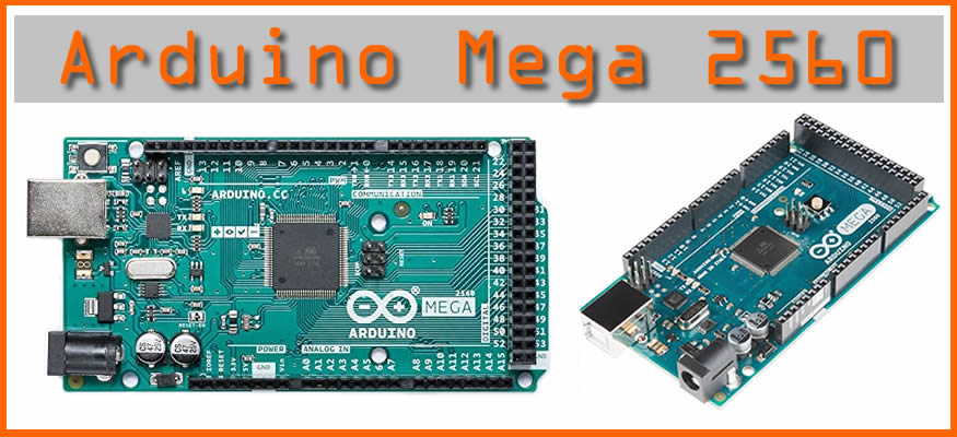
What is Arduino Mega 2560?
Arduino Mega 2560 is an open-source based on the Microchip ATmega2560 developed by Arduino. cc. The current version of Arduino Mega 2560 is an updated version of Arduino Mega. It 54 digital input/output pins, 16 analogue inputs, 4 UARTs (hardware serial ports), a 16 MHz crystal oscillator, a USB connection, a power jack, an ICSP header, and a reset button. An Atmega2560 microcontroller is used to connect with external electronics circuits. Out of 54 I/O ports, 15 pins were used for PWM output. Each pin operates at a voltage of 5V providing a maximum of 50mA. It also supports serial communication using Tx and Rx pins. The board consists of all the essential things needed to support the microcontroller.
Mega 2560 is powered either by connecting to a PC via USB cable or battery or an AC-DC adapter, although it operates at voltages between 7V and 20 volts. The Mega 2560 board is compatible with most shields designed for the Uno and the former boards Duemilanove or Diecimila. Moreover, this microcontroller is programmable with the Arduino IDE common to all our boards and supports C programming.
Features:
- High Endurance Non-volatile Memory Segments
- Write/Erase Cycles: 10,000 Flash
- Atmel QTouch library support
- JTAG (IEEE std. 1149.1 compliant) interface
- Peripheral Features
- Real-time Counter with Separate Oscillator
- Programmable Watchdog Timer with Separate On-chip Oscillator
- On-chip Analog Comparator
- Interrupt and Wake-up on Pin Charge
- Other special features
- Power-on Reset and Programmable Brown-out Detection
- Internal Calibrated Oscillator
- External and Internal Interrupt Sources
- Six Sleep Modes: Idle, ADC Noise Reduction, Power-save, Power-down, Standby, and Extended Standby
Specifications:
- Microcontroller: ATmega2560
- Operating Voltage: 5V
- Input Voltage (recommended): 7-12V
- Input Voltage (limits): 6-20V
- Digital I/O Pins: 54 (of which 15 provide PWM output)
- Analog Input Pins: 16
- DC Current per I/O Pin: 40 mA
- DC Current for 3.3V Pin: 50 mA
- Flash Memory: 128 KB of which 4 KB used by the boot loader
- SRAM: 8 KB
- EEPROM: 4 KB
- Clock Speed: 16 MHz
Pinout of Arduino Mega 2560:
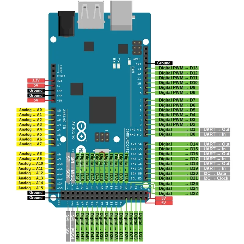
- Vin: This is the Arduino board’s input voltage pin, which is used to provide power from an external source.
- 5V: This pin on the Arduino board is utilised to provide a regulated power supply voltage to the board as well as onboard components.
- 3.3V: This pin on the board is used to deliver a 3.3V supply that is generated by the board’s voltage regulator.
- GND: The Arduino board is grounded using this pin on the board.
- Reset: The microcontroller is reset using this pin on the PCB. It’s for resetting the microcontroller.
- Serial Communication: RXD and TXD are serial pins that are used to transmit and receive serial data, respectively. Rx represents data transmission and Tx represents data reception. Serial 0 has RX(0) and TX(1), Serial 1 contains TX(18) and RX(19), Serial 2 contains TX(16) and RX(17), and Serial 3 contains TX(14) and RX(18), and Serial 3 contains TX(14) and RX(19) (15).
- External Interrupts pins: This pin of the Arduino board is used to produce the External interrupt and it is done by the pin numbers 0,3,21,20,19,18.
- I2C: I2C connection is supported by pins 20 and 21, where 20 represents SDA (Serial Data Line), and 21 represents SCL (Serial Control Line) (Serial Clock Line mainly used for providing data synchronisation between the devices)
- SPI Pins: This is the Serial Peripheral Interface pin, it is used to maintainSPI communication with the help of the SPI library. SPI pins include:
- MISO: Pin number 50 is used as a Master In Slave Out
- MOSI: Pin number 51 is used as a Master Out Slave In
- SCK: Pin number 52 is used as a Serial Clock
- SS: Pin number 53 is used as a Slave Select
- LED Pin: The board has an inbuilt LED using digital pin-13. The LED glows only when the digital pin becomes high.
- AREF Pin: This pin on the Arduino board is an analogue reference pin. An external power supply is utilised to provide a reference voltage.
Physical Characteristics of Arduino Mega 2560
The Mega 2560 PCB’s maximum length and width are 4 and 2.1 inches, respectively, with the USB connector and power jack protruding beyond the former. The board has three screw holes that allow it to be mounted to a surface or case. The distance between digital pins 7 and 8 is 160 mil (0.16″), which is not an even multiple of the other pins’ 100 mil spacing.
Shield Compatibility

Most shields made for other Arduino boards are compatible with the Arduino Mega. Before using a shield, make sure the shield’s working voltage is compatible with the board voltage. The majority of shields run at 3.3V or 5V, which is compatible with this board; however, shields that operate at a higher voltage may damage the board.
Furthermore, the shield’s header distribution must match the board’s pin distribution, allowing you to easily connect the shield to the board and get it working.
How to program Arduino Mega 2560?
The Arduino Mega 2560 can be programmed using the Arduino IDE (Integrated Development Environment), which supports C programming.The sketch is the code you create in the software, which is burned into the software and then sent to the board via USB cable.Because this board has a built-in bootloader, it eliminates the need for an external burner to burn the code into the board.The STK500 protocol is used by the bootloader to communicate.After you’ve finished compiling and burning the programme to the board, you can unhook the USB cord, which will turn off the board’s power. You can use the board’s power jack or Vin to power it up when you’re ready to use it in your project.
Another useful feature of the Arduino Mega is multitasking. However, the Arduino IDE Software does not enable multitasking, but you can build C programmes for this purpose using other operating systems such as FreeRTOS and RTX. This allows you to use your own custom build programme with the ISP connector, giving you more freedom.
Advantages:
- Low power consumption with quicker start-up
- 8-bit microcontrollers are less complicated than 32/64-bit equivalents, making them easier to use.
- QTouch Suite makes it simple to experiment with, develop, and debug your own touch applications.
- Adjacent Key Suppression technology, which is patented, enables unambiguous detection of key events.
Disadvantages:
- Limited amount of flash memory write cycles restricts the number of times images can be flashed when programmed to pc
- When compared to higher bit microcontrollers, it naturally lacks incremental performance.
Arduino Mega 2560 Applications:
The Arduino Mega 2560 is a great choice for applications that require greater memory and a larger number of pins on the board. The following are the most common applications of Arduino mega boards.
- Developing 3D printer
- Controlling and handling more than one motors
- Interfacing of number of sensors
- Sensing and detecting temperature
- Water level detection projects
- Home automation and security systems
- Embedded Systems
- IoT applications
- Parallel programming and Multitasking