
24V/12V Battery Voltage-Level Indicator
Occasionally, we fail to detect that the battery has been depleted, resulting in malfunctioning devices. By attaching this simple 24V/12V battery voltage indicator circuit across the battery, you can at any moment determine its voltage level.

This circuit can be used to test both 12V and 24V batteries. The 10 LEDs indicate the battery level. Each LED displays 10 percent of the battery’s voltage. Therefore, when LED1 through LED5 is lit, or when only LED5 is lit, the battery is about 50 percent charged. The circuit can assist with battery testing for a car, inverter, solar system, etc.
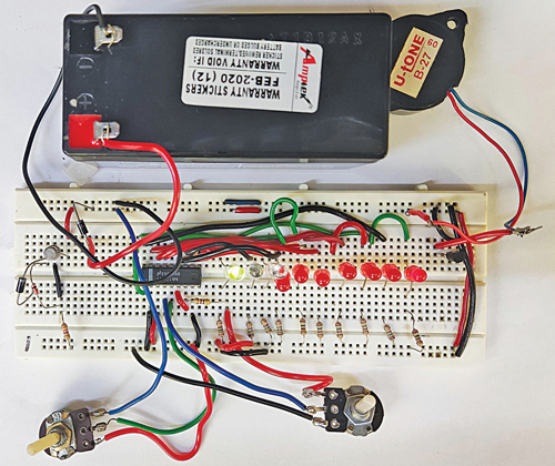
Author’s circuit on breadboard for 24V/12V Battery Voltage level indicator
The author’s circuit rigged on a breadboard is shown in Fig. 1 while the circuit’s block diagram is shown in Fig. 2.
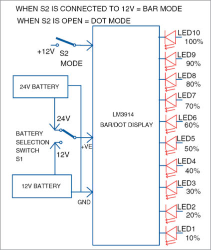
Block diagram of 24V/12V
As depicted in the block diagram, when LED1 alone illuminates, the battery level is only 10% full. With LED2 also lit, the remaining battery capacity is 20 percent, and so on. When all of the LEDs (LED1 through LED10) are lit, the battery is fully charged and the device is ready for usage.
The S1 switch is used to monitor either a 12V or 24V battery. Switch S2 allows for the selection of dot mode or bar mode display. In dot mode, only the final LED denoting the voltage illuminates, but in bar mode, all LEDs up to that point illuminate. The decision is yours to make.
Circuit and Working
The figure below depicts the circuit and operation of the battery voltage level indicator. It is constructed of an IC LM3914 dot/bar driver IC1, 1N4007 diodes D1 and D2, ten 5mm LEDs (LED1 through LED10), a 12.1V Zener diode (ZD1), a BC547 transistor T1, a BC557 transistor T2, preset VR1 and VR2, and a piezo buzzer PZ1.

Circuit diagram of 24V/12V Battery Voltage level indicator
The LED display, which includes LED1 through LED10, indicates the voltage level of the specified 24V or 12V battery. This display supports both dot mode and bar mode. Using the S2 switch, connect pin 9 of the IC to the positive terminal of the battery to display the voltage level in bar mode. To display the voltage level in dot mode, simply depress the S2 switch.
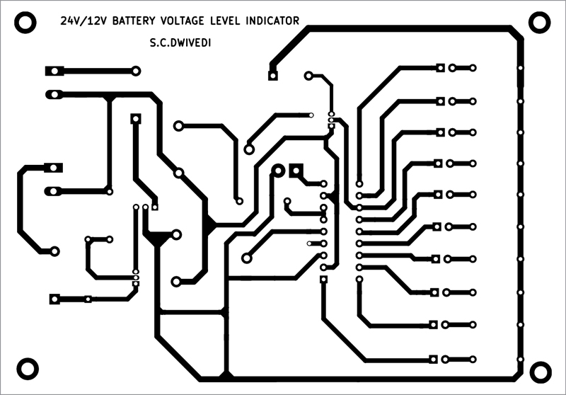
Single-side PCB layout of 24V/12V Battery Voltage level indicator component layout of the PCB
Download PCB and Component Layout PDFs: click here
Along with the BC547 transistor T1, the 12.1V Zener diode ZD1 is used to lower the 24V battery voltage to 12V. To run the circuit, pin 3 of IC1 is linked to the positive side of 12V, while pin 2 is connected to the ground.
To determine the battery’s voltage level, use two crocodile clips with approximately 30-centimeter-long wires soldered to each. One of the clips might be red and have a red wire soldered to it, while the other could be black and have a black wire soldered to it. Connect the red clip to the battery’s positive terminal and the black clip to its negative terminal. Flip switch S1 to determine the state of a 24V battery. The position of switch S2 will depend on whether a dot or bar display is desired.
Utilize the VR1 and VR2 settings to calibrate the circuit. And you may calibrate with a 30V variable power supply instead of a 24V battery. Connect 12V from the variable power supply to the circuit in place of the 24V battery. Adjust preset VR1 until LED1 just begins to shine. Now gradually increase the input DC voltage to 24V and witness the LED’s light. The first LED (LED1) will begin to emit light at 2.4V, the second at 4.8V, and so on. The final LED (LED10) will illuminate at 24V.
Following this calibration, the circuit is ready for operation. Connect a 24V battery to the circuit using the crocodile clips and set switch S1 to the 24V position to test its voltage. To see the voltage level in dot mode, keep switch S2 open. If LED9 is lit, the battery’s voltage is around 90 percent of 24V or approximately 21.6V. If LED10 is lit, the battery has been fully charged.

To view the battery voltage in bar mode, move switch S1 to the 24V position and activate switch S2. If LED1 through LED9 begin to illuminate, the battery’s voltage level is approximately 21.6V, or 90 percent of 24V. If all ten LEDs (LED1 through LED10) are illuminated, the battery’s voltage is 24V.
When the battery’s voltage decreases to 80 percent, a buzzer sounds to notify us that the battery needs to be charged. The piezo buzzer is driven by the base of transistor T2 linked to pin12 of integrated circuit IC1.
Construction and Testing
An actual-size, single-side PCB for the 24V/12V battery status indication and component configuration is illustrated in Fig below. After building the circuit on PCB, encapsulate it in a suitable plastic box. Switches S1 through S2 may be fixed on the back side of the cabinet. The assembled PCB may be attached inside the box’s front side in such a way that LED1 through LED10 are clearly visible.
Conclusion:
Hope this blog helps you to understand how to design a 24V/12V Battery Voltage-Level Indicator. We, MATHA ELECTRONICS will come back with more informative blogs.