
I am text block. Click edit button to change this text. Lorem ipsum dolor sit amet, consectetur adipiscing elit. Ut elit tellus, luctus nec ullamcorper mattis, pulvinar dapibus leo.
-8%Sold out


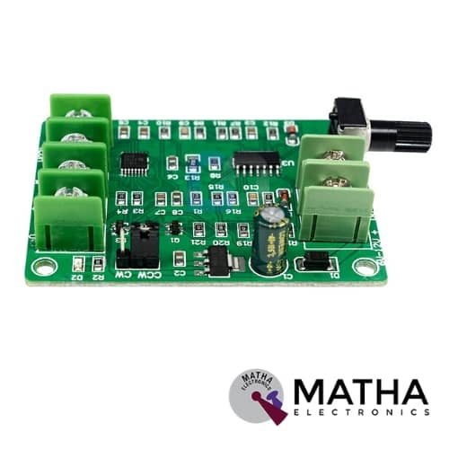
5V-12V DC Brushless Motor Driver Board Controller
Original price was: ₹2,225.00.₹1,999.00Current price is: ₹1,999.00. inc. GST
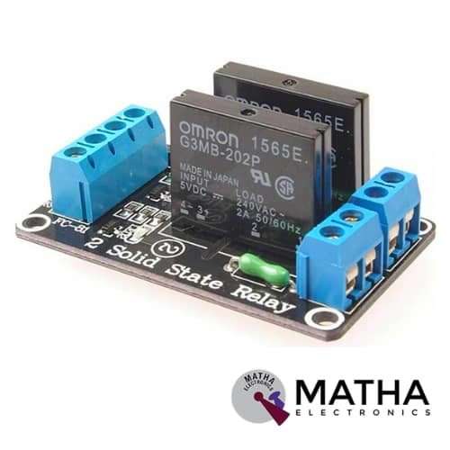
Solid Relay Module 2 channel 5v low level trigger for Arduino
Original price was: ₹500.00.₹475.00Current price is: ₹475.00. inc. GST
Solid Relay Module 1 channel 5v low level trigger for Arduino
Original price was: ₹300.00.₹275.00Current price is: ₹275.00. inc. GST
- 5V Solid State Relay
- Output With resistive fuse 240V 2A.
- Input Power: 5V DC (160MA).
- Input control signal voltage: 0 – 2.5V state low relay OFF/3.3V – 5V state high relay ON
- Working current: 12.5mA.
- Trigger voltage: 3.3-5V.
- Trigger current: 2mA.
- Rated output load: 100V to 240V AC (50Hz/ 60Hz) 2A per channel
- Rated input power: 5V, 160mA (all channels ON)
- Triggered at Low level (or Active Low)
- Separate LEDs showing the status of each Solid-State Relay
- Input control signal:
-Low Signal (Solid-State Relay ON / CLOSE), 0V- 2V or GND
-High Signal (Solid-State Relay OFF / OPEN), 3.3V – 5.0V or leave it floating
- Used in PLC control, home intelligent control, industry, electronic DIY etc.
- Dimension: 25mm x 34mm x 22mm
Out of stock
Description
A solid-state relay (SSR) is simply an IC that functions as a mechanical relay. The only difference between this SSR with the mechanical relay is that there is no moving contact in a Solid-State Relay. This SSR allows us to control high-voltage AC loads from lower voltage DC control circuitry. This is achieved by using infrared light as the ‘contact,’. In short, a solid-state relay is just an IR LED and a photometric enclosed into a little box. Thus we make use of the Phototriac coupler to turn it ON and OFF.
Solid-state relays offer numerous advantages over mechanical relays. One such advantage is that they can be switched by a much lower voltage and at a much lower current than most mechanical relays. Also, as there are no moving contacts, solid-state relays switched much faster and for much longer periods without wearing out. This 1-Channel Solid-State Relay Module is compatible with Arduino and hence interfaced easily.
Triggering at a high level indicates that there exists a forward voltage between a signal triggering terminal (CH1) and negative supply voltage. This usually connects positive supply voltage and triggering terminal together. When the triggering terminal contains a positive supply voltage or reaches the triggering threshold voltage, the relay will pull in.
While triggered at a low level resembles 0V voltage between the signal triggering terminal (CH1) and negative supply voltage. Or the voltage at the triggering terminal is lower than the positive supply voltage. Thus lowers to a triggering voltage, and the relay will pull in. It generally connects negative supply voltage and triggering terminal together. These relay module offers a wide range of applications in AC circuits as a TRIAC but offers only limited applications in DC. Along with that, this relay is suitable to control the AC load, not for DC load.
Reviews (0)
Shipping & Delivery

Related products

1 CHANNEL 5V RELAY
- 1 channel relay board
- Operating voltage: 5V
- Maximum current: 2 A
- Relay contact current capacity of 10A @250 V AC/10A@ 30V AC
- configured as SINGLE POLE DOUBLE THROW( SPDT)
- LED status indicates relay ON/OFF state.
- Standard TTL level logic controlled
- One normally closed and one normally opened contact
- Compatible with any 5V microcontroller
- Dimension: 43*17*17mm
- Weight: 150gm


10D OF 9-AXIS GY-87
- Power supply: DC 3.3V TO 5V
- 3 Axis Gyro+ Acceleration+ Magnetic field
- Air pressure module
- Inbuilt ultra-low noise linear LDO voltage regulator
- Inbuilt onboard filters. which reduce noise from motor and another high current
- Communication: I2C protocol
- Power LED
- Designed for 5V logic
- Can easily select two I2C addresses for MPU6050 by soldered jumper
- Dimension: 2.2*1.7cm
- Size: 6gm

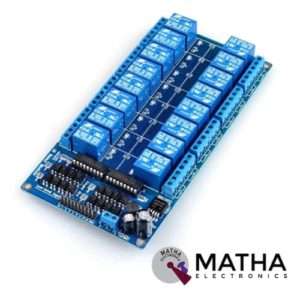
16 CHANNEL 12V RELAY
- 16 channel 12V relay board
- Operating voltage: 12V
- Supply current: 0.2 A
- Relay contact current capacity of 10A @250 V AC/10A@ 30V AC
- Optocoupler protection
- LED status indicates relay ON/OFF state.
- The 10-16 road can be any full-on/off or any road
- Common terminal(com) in each rely is user friendly and can be accessed by different signal
- Normally closed or normally open with each port
- Strong anti-jamming ability and stable performance
- The on-board power supply module doesn’t need any external power
- Dimension: 180*90*20mm
- Weight: 100gm

6-30V 1-Channel Power Relay Module with Adjustable Timing Cycle
- Operating voltage: 6 - 30V DC
- 1 Channel delay trigerred relay module
- Delay time: 0.1 second ~ 999 minutes
- Seven Segment Display
- Operating voltage: DC 6V-30V (supports micro USB 5V power supply)
- Trigger signal source: high-level trigger (3V-24V) signal ground and system to improve the system's anti-jamming capability (also short-circuit altogether)
- Output capability: it can control the device within DC 30V 5A or within AC 220V 5A
- Quiescent current: 20mA
- Operating current: 50mA
- Service life: more than 100,000 times
- Working temperature: -40°C-85°C
- With optocoupler isolation, enhanced anti-jamming capability, industrial grade circuit board, set parameters for memory after power failure.
- Dimension: 6.2 * 3.8 * 1.7cm
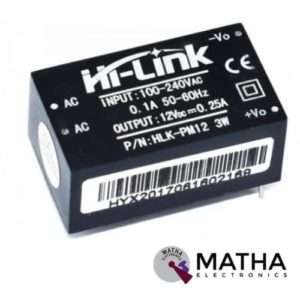

AC-DC Power Module HLK-PM12 230V to 12V /3W
- Rated input voltage: AC 100V -230V
- Input voltage range: 90V -264V AC
- Maximum input current: <0.2A
- Input current surge: <10A
- Maximum input voltage: <270V AC
- Input Low Voltage Efficiency Vin=110V AC,Output full-load≥ 69%
- Input High Voltage Efficiency Vin=220V AC,output full-load≥ 70 %
- Short-term maximum output current: ≥1000 mA
- Long-term reliability
- Voltage Regulation: ±0.2%
- Load Regulation: ±0.5%
- Ultra-thin and small module
- High efficiency, high power density
- Low ripple and low noise
- Output overload and short circuit protection
- Working temperature: – 20 degrees to +60 degrees Celsius
- Storage temperature: -40 degrees to 80 degrees Celsius
- Relative humidity: 5-95%
- Cooling way: Natural cooling
- Atmospheric pressure: 80-106Kpa
- Weight: 21g
- Size: 38x23x18mm
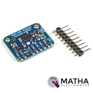

ADXL345
- Supply voltage: 3.3V/5V
- Communication type: I2C/SPI
- Sensing range: +/-2G to +/-16G
- Sensitivity
- X: 28.6 LSB/G
- Y: 31.2 LSB/G
- Z:34.5 LSB/g
- On-board LDO voltage regulator
- Resolution: 13 bit
- Single tap/double-tap detection
- Embedded memory management system with FIFO
- 10000g shock survival
- Low power consumption as low as 23 µA in measurement mode and 0.1 µA in standby mode at VS = 2.5 V (typical)
- 3-axis MEMS accelerometer
- Ideal for noisy power environment
- Operating temperature: -40 degrees to 85 degrees Celsius
- Dimension: 28*14mm
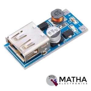

DC-DC BOOST MODULE 0.9V-5V/5V 600MA USB MOBILE Power Supply Module
- Ultra-compact PFM chip
- Module properties: nonisolated step-up module
- Input voltage: 1v-5v
- Output voltage: 5.1v-5.2V
- Output current: rated 1A-1.5A
- Efficiency: 96%
- Output ripple: 30mv for 20M bandwidth
- Switching frequency: 500khz
- Voltage indication for led lights with load( for less than 2.7v led indicator off)
- Operating temperature:-40 degrees to 85 degrees Celsius
- Full load temperature rise: 30 degrees Celsius
- Quiescent current: 130ua
- Load regulation: +/-1%
- Voltage regulation: +/-0.5%
- Dynamic response speed: 5% 200Us
- Short circuit protection
- Reverse polarity protection
- Dimension: 2.5*1.8*1.8gm
- Weight: 400gm

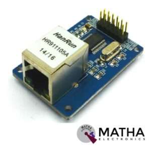
ENC28J60 ETHERNET MODULE
- ENC28J6 Ethernet chips, SOP28 package
- Operating voltage: 3.1V to 3.6V (3.3 V typical)
- Operating temperature: -40 degree to +85 degree Celsius
- IEEE 802.3 compatible Ethernet controller
- Buffer size: 8Kb
- Supports full and half-duplex mode
- SPI interface with a clock speeds up to 20MHz
- Programmable automatic rejection of erroneous packets
- Programmable automatic retransmit on a collision
- Programmable padding and CRC generation
- 25 MHz crystal oscillator
- Clock out the pin with a programmable presale
- Ethernet LAN module for Arduino/AVR/LPC/STM3
- 5V tolerant inputs
- SPI interface
- Led power indicator
- Dimension: 58*34*17mm
Reviews
There are no reviews yet.