
Power supplies are essential for the majority of products and devices. When constructing a circuit, ignoring the power supply component can occasionally result in catastrophic failure, which is undesirable. This is particularly important when creating a product. If the user uses a power supply with a higher output voltage than the device’s rated voltage, the product may be damaged. In such instances, you must equip your circuit with an overvoltage protection unit to prevent its failure. This is an SCR and Zener diode-based circuit for overvoltage protection.
Components required
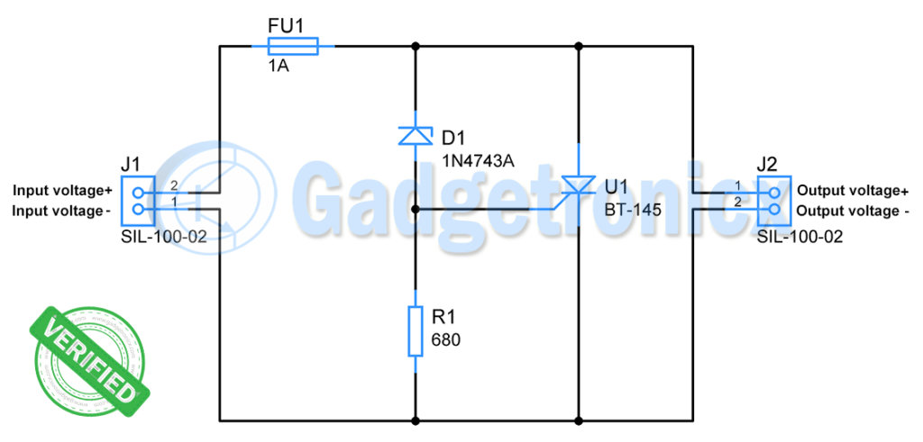
- SCR ( BT-145-800R )
- Zener diode(1N4743A)
- Fuse(1A)
- Resistor(680Ω)
Silicon controlled rectifier ( SCR ):
It is a three-terminal device featuring Anode, Cathode, and Gate terminals. When reverse-biased, it functions as a normal PN junction diode. In a forward biassed state, however, the gate current determines the flow of current through the anode. When a specific (unique to each SCR) current runs through the gate, the SCR behaves like a typical PN junction diode. At this point, current flows from Anode to Cathode through the SCR. This also results in a voltage drop between the anode and cathode due to the forward voltage of the SCR, which normally falls to 1V.

Zener diode:
In contrast to conventional PN junction diodes, it permits current to flow in reverse when a reverse voltage is placed across it. It is referred to as Zener voltage. In addition to permitting reverse bias current flow, zeners maintain the Zener voltage across their terminals. To accomplish this, it must be provided with a constant current known as Zener current. Zener current should not exceed its limit; else, the device will be destroyed.

Working of Overvoltage protection circuit:
- This circuit is designed to safeguard the connected circuit from voltages above 13V. It is designed for use with 12V circuits and devices. In general, 12V electronics can tolerate voltages up to 13V. So it will establish protection above 13V and provide the power supply with the appropriate operating room.
- In this circuit, J1 is used to connect the power supply, while J2 is used to connect the device/circuit that must be powered and protected.
- When the supply voltage is within 13V, the Zener will not conduct current and the SCR will be in a non-conducting state. When the power supply voltage exceeds 13V, the Zener diode begins conducting, allowing current to flow through it.
As indicated previously, the Zener diode current should be limited. The typical Zener current for 1N4743A, according to the datasheet, is 19mA. We may determine the required resistance using Ohm’s law.
Vz = 13v
Iz = 19mA
R = Vz / Iz
=680Ω
Therefore we have fixed R1 as 680Ω.
This Zener current and voltage across the resistor activate the SCR gate terminal. According to the datasheet, the gate current required to switch ON the SCR (BT-145-800R) is 5mA. Therefore, the Zener current forces the SCR to conduct current by triggering it.
When SCR is activated, it behaves as a short circuit, resulting in a massive current flow from Anode to Cathode. As noted previously, the voltage across it decreases, hence there will be no voltage at the output. This protects the circuit or device connected to terminal J2 as a result.
This enormous current flow continues until the source voltage or J1 voltage falls below 13V. When the current from the power source surpasses 1A, the Fuse will break its contact, providing further circuit protection. This blocks the flow of current.
Since many power sources lack an internal current limiting or short circuit protection feature, the fuse is vital. The current rating of the fuse should be smaller than the short circuit current of the power supply that the user may employ to power this circuit. This will ensure the successful termination of the current path when the maximum short circuit current threshold of the power supply is reached.
.
Note:
- Substitute your desired protection voltage for the Zener diode of Zener voltage
- The input voltage should not exceed Zener and SCR’s absolute maximum ratings.
Conclusion
Hope this blog helps you to understand how to design an overvoltage protection circuit. We, MATHA ELECTRONICS will come back with more informative blogs.