
A Quick Overview of RFID Technology
RFID is a technology-based identification method that identifies objects solely through the tags that are attached to them, without the need for direct line of sight between the tags and the tag reader. Radio communication between the tag and reader is all that is required.
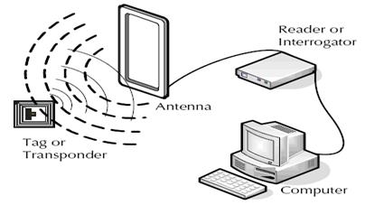
A Basic RFID System:
3 Main Components of an RFID System
- An RFID tag: A silicon microchip and a tiny antenna are installed on a substrate and enclosed in various materials, such as plastic or glass, with an adhesive on the back so that it can be connected to things.
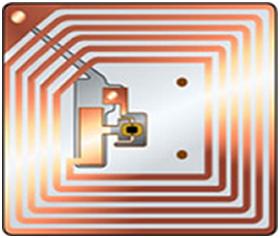
RFID Tag
- A reader: A reader is a device that communicates with tags and gets information from them. It is made up of a scanner and antennae for sending and receiving signals.
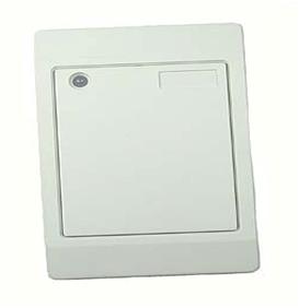
An RFID Reader
- A Processor or a Controller: The host computer, which receives reader input and processes the data, may have a Microprocessor or a Microcontroller.
2 Types of RFID Systems:
- Active RFID system: An active RFID system is one in which the tag has its own power supply, such as a battery or an external power supply. The lifespan of the power devices is the only restriction. These technologies can be used to track expensive commodities like autos across greater distances.
- Passive RFID system: In these types of systems, electricity is transferred from a reader antenna to the tag antenna, which powers the tag. They are utilized for transmission across short distances.
Since it is most frequently utilized in everyday applications like those in retail market organizations, the passive RFID system is our main focus here.
How the Passive RFID System Works:
Either an EM wave capture method or an inducting coupling approach can be used to power the tag. Let’s use these two approaches to gain a basic understanding of the system.
- A Passive RFID system using the Induction coupling method:
According to this method, the RFID tag is powered by the reader through inductive coupling. A coil that is attached to an AC source creates a magnetic field surrounding the reader. By virtue of Faraday’s law of induction, an electromotive force is induced in the tag coil when it is placed close to the reader coil. A magnetic field is created around the coil as a result of the EMF flowing electricity through it.
As a result of Lenz law, the magnetic field of the tag coil opposes that of the reader, increasing the current flowing through the reader coil. This is taken as the load information by the reader. This technique is appropriate for very close-proximity communication. A rectifier and filter combination is used to convert the AC voltage that appears across the tag coil to DC.
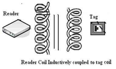
Passive RFID using Inductive Coupling
- A Passive RFID system using EM wave propagation method:
Electromagnetic waves are transmitted by the antenna in the reader and are picked up by the antenna in the tag as a potential difference across the dipole.
To obtain DC electricity, this voltage is rectified and filtered. A portion of the received signal is reflected by the reception antenna because it is maintained at a different impedance. The reader picks up this mirrored signal and acts upon it appropriately.
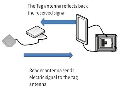
Passive RFID using EM-wave transmission
An Idea about How the Active RFID System Works:
The reader uses an antenna to transmit a signal to the tag in an operational RFID system. Along with the data stored in its memory, the tag gets this information and delivers it again. This signal is received by the reader and sent to the processor for additional processing.
An Active RFID system
A Working Example of RFID Application – An RFID Based Attendance System
Let’s now look at a realistic solution to our second issue: employing RFID technology to maintain and verify a database of members of an organization.
Each employee of the organization is issued an identification card, and when that card is swiped across a reader, the information on the card is compared to the database’s records to determine whether the person is in attendance.
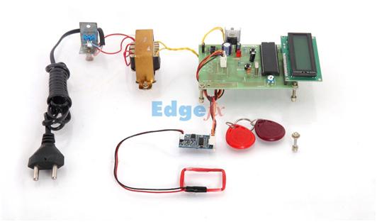
Block Diagram

The passive RFID system with inductive coupling is utilized throughout the entire system. A 125 kHz carrier signal is sent to the tag coil as the RFID card (tag) is swiped against the RFID reader; the tag coil receives this signal and modulates it. The reader, which is connected to the microcontroller, receives this modulated signal. When this data is received, the microcontroller is programmed to compare it to the information in the current database. If the data matches, the microcontroller-interfaced LCD will display pertinent information about that specific person.
Conclusion
I hope all of you had got a brief idea about the RFID system and a simple application. We MATHA ELECTRONICS will be back soon with more informative blogs.