
We are living in a technology-based society where we have lots of innovative ideas day by day. These new innovations in Electronics-based projects come as an ever-growing network that strives constantly to share and gather insight on the latest trends in the present Era

In this blog, we discuss the MAX30100 pulse oximeter sensor. We’ll connect this sensor to our Arduino and see how it works. This will be a basic project, and the circuit diagram and code will be provided below.
The majority of the work in these types of sketches is done by libraries; all we have to do is initialize the code, libraries, and functions. You can make your own PCB in the shape of a watch or something similar that is commercially available. BPM and SPO2 levels can be measured using this method. Then we’ll design a PCB and place an order with JLCPCB ($2 for 5 pcs).
Pulse Oximeter Sensor
The Pulse oximeter, often known as a Pulse Ox, is an electrical device that detects the oxygen saturation in red blood cells. Pulse oximeters can be placed on the fingers, the forehead, the nose, the foot, the ears, or the toes.
It is a non-invasive medical device that uses spectrophotometry to determine the proportion of oxygenated hemoglobin pulsating through a network of blood capillaries using a sensor commonly connected to a finger to detect the oxygen saturation of circulating arterial blood in an individual. This sensor was designed to detect BPM (beats per minute) and Spo2 (seconds per second) (Oxygen level in blood).
Normally, a typical level of oxygen is 95 percent or above. Normal levels can be as high as 90% in persons with persistent lung illness or sleep apnea. A pulse oximeter’s “SpO2” reading

Difference Between BP and BPM:
Your heart rate is the number of times your heart beats per minute (BPM), whereas your blood pressure is the force with which your blood flows through your vessels (BP).

Components Required
- Arduino UNO
- 16X2 LCD (With I2C adapter)
- MAX30100 sensor
- Wires and breadboard
- Custom PCB
Arduino Uno:
Arduino Uno is an open-source based on the Microchip ATmega328P developed by Arduino. cc. It contains 14 digital I/O pins (six of which may be used as PWM outputs), six analog inputs, a 16 MHz ceramic resonator (CSTCE16M0V53-R0), and a USB connection, a power connector, an ICSP header, and a reset button. It comes with everything you need to support the microcontroller; simply connect it to a computer through USB or power it using an AC-to-DC converter or battery to get started.

Pulse Oximeter Sensor-MAX30100:

MAX30100 is a sensor that combines a pulse oximeter and a heart rate monitor. It’s an optical sensor that measures the absorbance of pulsating blood through a photodetector after emitting two wavelengths of light from two LEDs – a red and an infrared one.
It runs on 1.8V and 3.3V power sources, and it may be turned down by software with very little standby current, allowing the power supply to be connected at all times.
Features:
- Measures absorbance of pulsing blood
- I2C interface plus INT pin
- Tiny 5.6mm x 2.8mm x 1.2mm 14-Pin Optically Enhanced System-in-Package
- Ultra-Low-Power Operation Increases Battery Life for Wearable Devices
- Programmable Sample Rate and LED Current for Power Savings
- Ultra-Low Shutdown Current (0.7µA, typically)
- Advanced Functionality Improves Measurement Performance
- High SNR Provides Robust Motion Artifact Resilience
- Integrated Ambient Light Cancellation
- High Sample Rate Capability
- Fast Data Output Capability
Working of MAX30100 Pulse Oximeter and Heart-Rate Sensor
The device has two LEDs, one of which emits red light and the other of which emits infrared light. Only infrared light is required to determine pulse rate. The amounts of oxygen in the blood are measured using both red and infrared light.
When the heart pumps blood, the amount of oxygenated blood in the blood increases as a result of having more blood. The volume of oxygenated blood reduces when the heart relaxes. The pulse rate is calculated by measuring the time between the increase and decrease of oxygenated blood.
It turns out, oxygenated blood absorbs more infrared light and passes more red light while deoxygenated blood absorbs red light and passes more infrared light. The MAX30100’s main purpose is to read both light sources’ absorption levels and store them in a buffer that can be read using the I2C communication protocol.
Circuit Diagram:
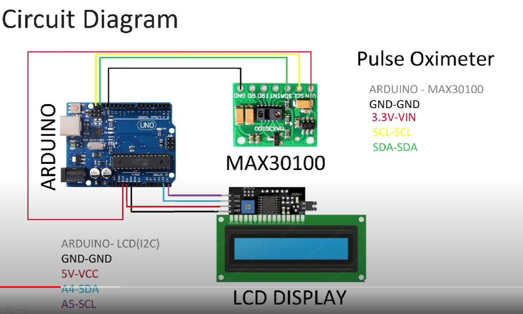
Since both the LCD and the sensor communicate via I2C, we may connect them to the same A5 (SCL) and A4 (SDA) pins. We can use 127 devices in parallel because the Arduino Uno i2c has 7-bit addresses. We can use +5v to power the sensor and LCD. The microcontroller is responsible for the rest of the job. Here you may find circuit diagrams, code, and Gerber files.
PCB Designs:
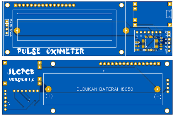
I’m trying to keep this DIY design as simple as possible, so I’m using an Arduino Nano MCU, a 16*2 LCD, and a MAX30100 with a charging circuit on the PCB.
The schematics have been tested, but the LCD will only operate with an I2C interface. Pins are just used to help people understand what they’re doing. Download the Gerber files from here if you wish to use the same design as mine.
Code:
| #include <LiquidCrystal_I2C.h> #include <Wire.h> #include “MAX30100_PulseOximeter.h” #define REPORTING_PERIOD_MS 1000 LiquidCrystal_I2C lcd(0x27, 16, 2); byte smile[] = { B00000, B00000, B01010, B00000, B10001, B01110, B00000, B00000 }; byte mod[] = { B00000, B00000, B01010, B00000, B11111, B00000, B00000, B00000 }; byte sad[] = { B00000, B00000, B01010, B00000, B01110, B10001, B00000, B00000 }; PulseOximeter pox; uint32_t tsLastReport = 0; void onBeatDetected() { Serial.println(“Beat!!!”); } void setup() { Serial.begin(115200); lcd.begin(); lcd.backlight(); lcd.createChar(1 , smile); lcd.createChar(2 , mod); lcd.createChar(3 , sad); lcd.setCursor(0, 0); lcd.print(” Pluse”); lcd.setCursor(0, 1); lcd.print(” Oximeter”); delay(2000); if (!pox.begin()) { Serial.println(“FAILED”); for (;;); } else { Serial.println(“SUCCESS”); } pox.setIRLedCurrent(MAX30100_LED_CURR_7_6MA); pox.setOnBeatDetectedCallback(onBeatDetected); } void loop() { pox.update(); if (millis() – tsLastReport > REPORTING_PERIOD_MS) { lcd.clear(); lcd.setCursor(0 , 0); lcd.print(“BPM : “); lcd.print(pox.getHeartRate()); lcd.setCursor(0 , 1); lcd.print(“Sp02: “); lcd.print(pox.getSpO2()); lcd.print(“%”); tsLastReport = millis(); if (pox.getSpO2() >= 96) { lcd.setCursor(15 , 1); lcd.write(1); } else if (pox.getSpO2() <= 95 && pox.getSpO2() >= 91) { lcd.setCursor(15 , 1); lcd.write(2); } else if (pox.getSpO2() <= 90) { lcd.setCursor(15 , 1); lcd.write(3); } } } |
Measurements:
Simply place your finger gently on the Max30100 sensor to measure BPM and oxygen level. It will start the system on its own. After 10 seconds, you will have a complete and accurate reading.
You can also utilize a prototype PCB Gerber file to make this project more practical, with built-in power and a small footprint. Also, a big thank you to JLCPCB for sponsoring this initiative.

Hope this blog helps you to understand how to interface MAX30100 pulse oximeter sensor with Arduino. We, MATHA ELECTRONICS will come back with more informative blogs.