
How to design Automatic Fish Feeder Using Arduino Nano?
There are all kinds of automatic fish feeders on the market, however, most just dump the allotted food in one lump and typically can’t be programmed for an entire week of use. In this very busy life, there are chances when I forget to feed fish and spend large amounts of time away from home.

In this article, I will make an automatic feeding device for fish in an aquarium. This tool uses Arduino nano as the main controller to drive the servo in the feeding process.
I will use this tool in an aquarium that I just bought a few days ago. I worry if I forget to feed the fish when I go out for activities. so I hope with this tool the fish can eat regularly.
Component and Material
- Arduino Nano
- Real-time clock (DS1302),
- Step down DC to DC LM2596
Arduino Nano
Arduino Nano version 3 is an open-source small embedded development board based on the Microchip ATmega328 SMD package developed by Arduino. cc. Meanwhile, the current version of Arduino Nano comes with a mini USB port. The current version of Arduino Nano comes with 14 digital I/O pins, 8 analog pins, an ICSP header, and 16 MHz ceramic resonators. And an Atmega328 microcontroller is used to connect with external electronics circuits. Out of 14 I/O ports, 6 pins were used for PWM output. This Arduino board lacks a DC power jack. Each pin operates at a voltage of 5V providing a maximum of 40mA. It also supports serial communication using Tx and Rx pins. As the DC Power Jack is not available on this Board, power can be given through Mini USB Cable.

Real-time clock (DS1302),
DS1302 trickle-charge timekeeping chip consists of a real-time clock/calendar (RTC). It’s an 8-pin gadget that uses 31 bytes of battery-backed SRAM to display a full binary-coded decimal (BCD). Address and data are serially transmitted in this IC over an I2C bidirectional bus. On the I2C bus, the DS1302 acts as a slave device. The DS1302 is a low-power clock that provides certified data for seconds, minutes, hours, days, dates, months, and years. It automatically modifies the end date of each month, particularly for months with less than 31 days, taking into account leap year corrections. The clock has an AM/PM indicator and works in either a 24-hour or 12-hour mode.

Step down DC to DC LM2596
LM2596 3A step-down module is a DC to DC buck converter step-down power module with a high precision potentiometer. LM2596 is an easy-to-use, nonsynchronous, step-down DC-DC converter with a wide input voltage range up to 35 V. It is capable of driving a load up to 3A with high efficiency. But heat sinks are used in a certain case when the output current required is greater than 2.5(or output greater than 10W). LM2596 3A step-down module takes the higher input and converts it into lower output voltage, thus providing excellent line and load regulation.

Step 1: Skema Dan Layout

Step 2: Insert Components Into PCB

Using the schematic as a guide, place the components one by one into the PCB.
Install the SMD components first to help the process go faster. After that, simply install the THT components one by one, beginning with the shortest. Attach the Arduino, RTC, and DC to DC modules to the PCB at the end.
Step 3: Modify Servo

The servo motor needs to be modified so that it can rotate more than 360 degrees.
Here’s how to modify it:
- Set the servo motor to the 90-degree position.
- Disassemble the servo
- then cut the servo motor position sensor axle
- reassemble the servo motor case
Modification result:
- If the servo is set < 90 degrees, the servo will rotate to the right.
- If the servo is set = to 90 degrees, the servo will be silent because the position sensor is always at 90 degrees.
- If the servo is set >90 degrees, the servo will rotate to the left.
- When turning right or left, servo rotation can be more than 360 degrees
Fish feed mechanics consist of two parts. Part of the feed container and gear for removing feed.
Here’s how to install it:
- Attach the servo to the housing through the hole in the front of the housing
- Attach the gear to the servo using glue
- because the feed outlet hole is too big, I partially closed the hole
Step 4: Programming


There are two stages of programming that must be done:
- Set the RTC time according to the current time
- Programming Arduino with automatic fish feed program
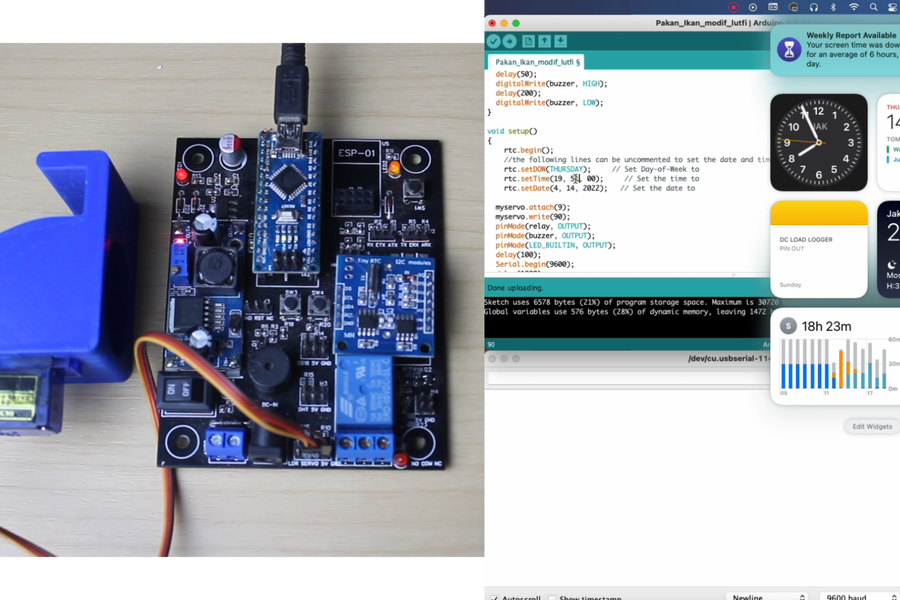
Programm the RTC time according to the current time:
- See the function in the setup part; you can set the time on the RTC starting from the day, date, and time in this area:
rtc.setDOW(THURSDAY); // Set Day-of-Week to .. rtc.setTime(19, 59, 00); // Set the time to .. rtc.setDate(4, 14, 2022); // Set the date to .. |
- Upload program to Arduino
- check the serial monitor to make sure the time has been sent successfully
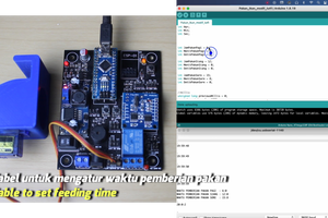
Programming Arduino with automatic fish feed program:
Still using the same program, but the function to set the time is made a comment so that it is not read by the program.
| ///rtc.setDOW(THURSDAY); // Set Day-of-Week to .. //rtc.setTime(19, 59, 00); // Set the time to .. //rtc.setDate(4, 14, 2022); // Set the date to .. |
- Set the feeding time by changing the following variables:
| //morning feed time int JamPakanPagi = 6; int MenitPakanPagi = 0; int DetikPakanPagi = 0; //afternoon feed time<br> int JamPakanSiang = 12; int MenitPakanSiang = 0; int DetikPakanSiang = 0; //evening feeding time int JamPakanSore = 19; int MenitPakanSore = 0; int DetikPakanSore = 0; |
- Adjust the amount of feed given. Amount of fish feed given = servo ignition time
| void Beri_pakan() { buzz(); delay(500); buzz(); delay(700); buzz(); myservo.write(80); //delay to adjust the amount of feed given delay(400); myservo.write(90); buzz(); delay(500); buzz(); } |
- Upload program to Arduino
Step 5: Assembly

After all of the materials have been prepared, the assembly procedure can begin. Here’s how to put it together:
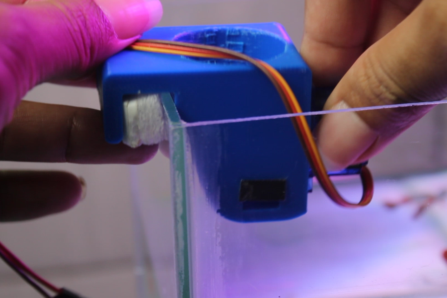
- Attach the fish feed mechanism to the aquarium’s edge, using a wedge to keep it firmly in place.
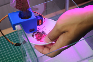
- As needed, refill fish feed.
- The servo motor should be connected to the Arduino module in the following order: Ground is brown, 5V is red, and data is yellow (see picture)
- connect the Arduino to the power source
This completes the automatic fish feed project using Arduino
Step 6: Results
