
ARDUINO NANO-A COMPLETE GUIDE
Nowadays the electronic devices are becoming compact, flexible, and cheap that are capable of doing more function as compared to their predecessors. A Microcontroller was introduced as a new innovation in the electronics industry. Designed with the purpose of making our tasks easier, with minimum effort, and gives maximum output. Here, we are going to discuss about one of the popular microcontroller Arduino Nano, what is this about, the main features, working, technical specifications and everything you need to know.

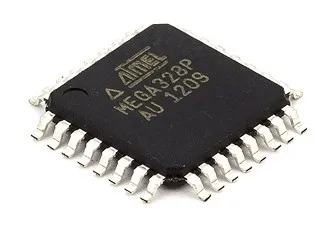
The Arduino Nano development board is one of the most popular Arduino boards, having been introduced in 2008.. It is based on the ATmega328 8-bit microcontroller by Atmel (Microchip Technology). The Atmega328 has a built-in bootloader, which makes flashing the Nano board with a programme simple
WHAT IS ARDUINO NANO?
Arduino Nano version 3 is an open-source small embedded development board based on the Microchip ATmega328 SMD package developed by Arduino. cc. Meanwhile, the current version of Arduino Nano comes with a mini USB port.The current version of Arduino Nano comes with 14 digital I/O pins, 8 analogue pins, an ICSP header, 16 MHz ceramic resonators. And an Atmega328 microcontroller is used to connect with external electronics circuits. Out of 14 I/O ports, 6 pins were used for PWM output. This Arduino board lacks a DC power jack. Each pin operates at a voltage of 5V providing a maximum of 40mA. It also supports serial communication using Tx and Rx pins. As the DC Power Jack is not available on this Board, power can be given through Mini USB Cable.

The Nano board is designed in such a way that the pins are breadboard friendly so that you can easily mount it on one for your DIY projects. After Arduino UNO, the most popular board in the Arduino line-up is probably the Arduino Nano. Both UNO and Nano are based on ATmega328P Microcontroller but Nano is significantly smaller in size compared to UNO.

SPECIFICATIONS:
- Microcontroller: Atmel ATmega328 SMD Package
- Operating Voltage (logic level): 5 V
- Input Voltage (recommended): 7-12 V
- Input Voltage (limits): 6-20 V
- Digital I/O Pins: 14 (of which 6 provide PWM output)
- Analog Input Pins: 8
- DC Current per I/O Pin: 40 mA
- Flash Memory: 32 KB (of which 2KB used by bootloader)
- SRAM: 2 KB
- EEPROM: 1 KB
- Clock Speed: 16 MHz
- Automatic reset during program download
- Power OK blue LED
- Green (TX), red (RX) and orange (L) LED
- Auto-sensing/switching power input
- Small mini-B USB for programming and serial monitor
- ICSP header for direct program download
- Standard 0.1” spacing DIP (breadboard friendly)
- Manual reset switch
- Dimensions: 0.70” x 1.70”
Atmega328P Microcontroller:
The Atmega328P is an 8-bit microcontroller with high speed and efficiency, based on the AVR (Audio Video Recorder) RISC (Reduced Instruction Set Computing) architecture. It’s widely considered as the most popular AVR controller. It has a lower power consumption than the Atmega328 Microcontroller.
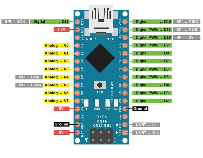
ARDUINO NANO PINOUT:
- Arduino Nano Power Pin :
- Vin: This is the Arduino board’s input voltage pin, which is used to provide power from an external source.
- 5V: This pin on the Arduino board is utilized to provide a regulated power supply voltage to the board as well as onboard components.
- 3.3V: This pin on the board is used to deliver a 3.3V supply that is generated by the board’s voltage regulator.
- GND: The Arduino board is grounded using this pin on the board.
- Arduino Nano Pinout- Analog Pins:
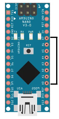
The Arduino UNO contains six analogue pins, but the Arduino Nano has eight, numbered A0 to A7. Up to 8 analog/digital sensors can be connected to the board. Analog pins are used to read the value of the analog/digital input that is used in the connection. Each of these analogue pins has a built-in ADC with a 2^10 bits-bit resolution (so it will give 1024 values).
- Arduino Nano Pinout- Digital Pins:

There are 14 digital I/O pins. The Arduino digital pins can read/output only two states: when there is a voltage signal and when there is no signal. This kind of input/output is usually called digital (or binary) and these states are referred to as HIGH or 1 and LOW or 0.
- Arduino Nano Pinout- PWM Pins:

- PWM Pins: These pins on the board are used to change the width of the pulse to convert a digital signal to an analogue signal. A PWM pin is one with the numerals 3,5,6,9,10, and 11.
- ICSP pins:
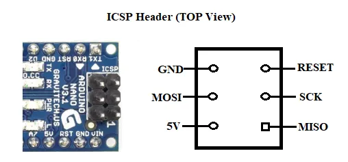
It stands for In-Circuit Serial Programming. We can programme the Arduino board’s firmware using these pins. The ICSP header is used to upload the firmware with the new functionality to the microcontroller.
- I2C pins:
It is the two-wire serial communication protocol. It stands for Inter-Integrated Circuits. The I2C uses two lines to send and receive data: a serial clock pin uses (SCL) and a serial data (SDA) (SDA) pin.
- SCL-It stands for Serial Clock. It is defined as the line that transfers the clock data. It is used to synchronize the shift of data between the two devices. The Serial Clock is generated by the master device.
- SDA-It stands for Serial Data. It is defined as the line used by the slave and master to send and receive the data. That’s why it is called a data line, while SCL is called a clock line.
Pin A4 & A5 signifies Serial Data Line (SDA) and Serial Clock Line (SCL)
- SPI pins:

SPI stands for Serial Peripheral Interface. It is used by the microcontrollers to communicate with one or more peripheral devices quickly.
- SS: Pin number 10 is used as a Slave Select
- MOSI: Pin number 11 is used as a Master Out Slave In
- MISO: Pin number 12 is used as a Master In Slave Out
- SCK: Pin number 13 is used as a Serial Clock
- OTHER PINS:
- Serial pins: These are also referred to as UART pins. It allows the Arduino board to communicate with a computer or other devices. To broadcast and receive data, the transmitter pin number 1 and receiver pin number 2 are used, respectively.
- External Interrupt Pins: This pin on the Arduino board is used to generate an external interrupt, and pin numbers 2 and 3 are used to do so.
- Reset: The microcontroller is reset using this pin on the PCB. It’s for resetting the microcontroller
- LED Pin: In the board, there is a built-in LED connected to digital pin 13. When this pin is set HIGH or 1, the LED turns ON. When the pin is set LOW or 0, the LED turns OFF.
- AREF Pin: This pin on the Arduino board is an analogue reference pin. An external power supply is utilised to provide a reference voltage.
HOW TO POWER UP ARDUINO NANO?

There are a couple of ways in which you can power the Nano board. The first and easy way is using the mini-B type USB Connector and the other one is usingVin power supply
Mini USB: The Mini USB is smaller than the micro USB but larger than the normal USB. This port is used to power the Nano board. It also allows us to programme the board by connecting it to the computer.
Vin: This is the Arduino board’s input voltage pin, which is used to provide power from an external source.
ARDUINO NANO MEMORY:
There are three different memories available in ATmega328P. They are:
- 32 KB of Flash Memory(2 KB of the Flash Memory is used by the bootloader code.)
- 2 KB of SRAM
- 1 KB of EEPROM
ARDUINO NANO PROGRAMMING:
The Arduino Nano can be programmed using the Arduino IDE (Integrated Development Environment), which supports C programming.
The board can be directly program from the Arduino IDE, connecting your NANO board to the PC using the USB mini (Nano side) to USB B-type (PC side) cable. You only need to download the free Arduino IDE software, which is accessible for all operating systems, or you may code it online using their Arduino Web IDE, which does not require any downloads or installations.
Here is link to download the Latest Arduino IDE Software
I hope you now have a basic understanding of Arduino programming. So, next, I’ll guide you through downloading and configuring Arduino IDE, as well as running your first code.
Steps to use the Arduino IDE
- Connect the board to the computer via a USB cable once the Arduino IDE has been installed on the PC. Now launch the Arduino IDE and choose the relevant board from the drop-down menu.
Tools>Boards>Arduino/Nano
- choose the correct Port by selecting
Tools>Port.
- Arduino Nano is programmed using Arduino programming language based on Wiring. To get started with the Arduino Nano board and blink the built-in LED, select the sample code from the drop-down menu.
Files>Examples>Basics>Blink.
- Once the example code (also shown below) is loaded into your IDE,click on the ‘upload’ button given on the top bar.
- Once the upload is finished, you should see the Arduino’s built-in LED blinking. Below is the preloaded example code for LED blinking
CODE:
| // the setup function runs once when you press reset or power the board void setup() { // initialize digital pin LED_BUILTIN as an output. pinMode(LED_BUILTIN, OUTPUT); } void loop() // the loop function runs over and over again forever { digitalWrite(LED_BUILTIN, HIGH); // turn the LED on (HIGH is the voltage level) delay(1000); // wait for a millisecond digitalWrite(LED_BUILTIN, LOW); // turn the LED off by making the voltage LOW delay(1000); // wait for a millisecond } |
OUTPUT:
After running the code, the onboard LED should start blinking according to the frequency of delay you set in code like this
APPLICATIONS:
- Prototyping of Electronics Products and Systems
- Multiple DIY Projects.
- Samples of electronic systems & products
- Automation and Control Systems
- Easy to use for beginner-level DIYers and makers.
- Projects requiring Multiple I/O interfaces and communications
Hello.
My name is Joe and it’s very interested to learn about the arduino nano as I am trying to learn from the beginning as I am a broad cast transmitter engineer and I like to begin learning the programming code..