
Construction & Working of a DC Motor
Electric motors are used in almost every industry and in a wide range of applications. Electric motors are available in a wide range of sizes and types. These motors can be selected based on their functioning, voltage, and applications. Using the proper motor with high-quality parts and performing regular maintenance keeps your motor running smoothly and protects endpoint equipment from wear and power spikes.
This article will teach you the working principle of DC motors, how they work? Also, we will talk about the construction of a DC motor in detail.
WHAT IS AN ELECTRIC MOTOR?
Electric motor is a machine which converts electric energy into mechanical energy usually by employing electromagnetic phenomena. . It works on the principle that when a current-carrying conductor is placed in a magnetic field, it experiences a mechanical force whose magnitude is determined by F = BIl Newton and whose direction is determined by Fleming’s Left-hand Rule.
The various types of electric motor differ in the ways in which the conductors and the field are arranged and also in the control that can be exercised over mechanical output torque, speed, and position. The following are the two main types of electric motors:
- AC motors, which are powered by alternating current
- DC motors, which are powered by direct current
Electric motors are available in a wide range of sizes and types. These motors can be selected based on their functioning, voltage, and applications.
DC Motor:
In DC Motors,Direct current electric energy is converted into mechanical rotational energy. You can also utilize the device in reverse to generate DC electrical power by turning a motor shaft (making the device function as a generator). The winding connections, in which how the two coils in the motor are coupled to each other, can be used to classify DC motors.

The operation of the DC motor is based on the principle that when a current carrying conductor is placed in a magnetic field, a mechanical force acts on the conductor. The magnitude of the force is given by,
F=BIl Newtons
The direction of this is given by the Fleming’s left hand rule.
Types of DC Motor
There are 4 major types of DC motor and they are,
- Series DC Motor
- Permanent Magnet DC Motor
- Shunt/Parallel DC Motor
- Compound DC Motors
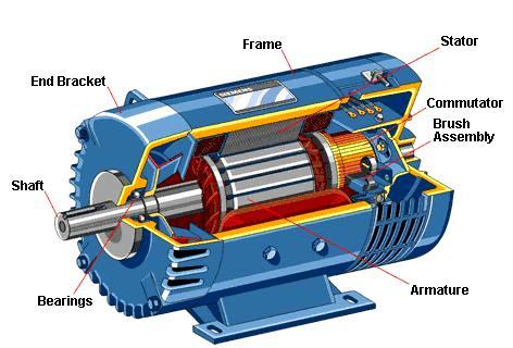
CONSTRUCTION OF DC MOTOR
Here is the schematic diagram of a DC Motor

A DC motor consists of six main parts, which are as follows
- Yoke
The yoke is the outside frame of a DC motor, which is a hollow cylinder composed of cast steel or rolled steel. The yoke is used for two purposes.
- It acts as a protective shell for the machine and supports the field pole core.
- It provides a path for the magnetic flux produced by the field winding.
- Magnetic Field System
A DC motor’s magnetic field system is the machine’s stationary component. It generates the majority of the magnetic flux in the motor. It’s made up of an even number of pole cores bolted to the yoke and field winding wrapped around them. The field system of a DC motor features salient poles, which extend inwards and each pole core has a curved surface on the pole shoe. The pole shoe has two functions.
- It provides support to the field coils.
- It reduces the reluctance of magnetic circuit by increasing the cross-sectional area of it.
To prevent eddy current loss, the pole cores are built of thin sheet steel laminations that are isolated from one another. The field coils are connected in series with one another, resulting in alternate north and south poles when current passes through them.
- Armature Core
The DC motor’s armature core is attached to the shaft and revolves between the field poles. It has slots on its outer surface and the armature conductors are put in these slots. The armature core is made up of soft steel laminations that are carefully clamped together and insulated from one another. The laminations are keyed directly to the shaft in small machines, whereas they are mounted on a spider in large machines. Eddy current loss is reduced by using a laminated armature core.
- Armature Winding
The insulated conductors are inserted into the armature core’s slots. Armature winding is the term for the connected arrangement of conductors. Wave winding and lap winding are the two types of armature windings employed.
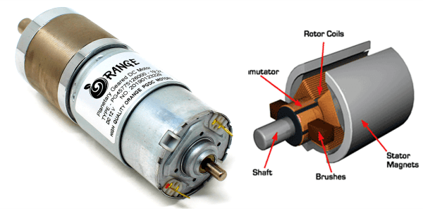
- Commutator
A commutator is a mechanical rectifier that converts direct current from a DC source into alternating current in the armature winding of a motor. The commutator is made of wedge-shaped copper segments insulated from each other and from the shaft by mica sheets. Each commutator segment is attached to the armature coils’ ends.
- Brushes
The brushes are mounted on the commutator and are used to inject the current from the DC source into the armature windings. The brushes are made of carbon and is supported by a metal box called brush holder. The pressure exerted by the brushes on the commutator is adjusted and maintained at constant value by means of springs. Through the carbon brushes and commutator, current passes from the external DC source to the armature winding.
WORKING OF DC MOTOR
Consider the two-pole DC motor depicted in the diagram. When the DC motor is connected to a DC supply from outside, the field coils are excited, forming alternate N and S poles, and current flows through the armature windings.

Under the N pole, all armature conductors carry current in one direction (say, into the plane of the paper), whereas under the S pole, all conductors carry current in the other direction (say out of the plane of the paper). As each conductor carrying a current and is placed in a magnetic field, hence a mechanical force acts on it.

By applying Fleming’s left hand rule, it can be seen that the force on each conductor is tending to move the armature in anticlockwise direction. The force on all the conductors add together to exert a torque which make the armature rotating. When the conductor moves from one side of a brush to the other, the current in the conductor is reversed and at the same time it comes under the influence of next pole of opposite polarity. As a result of this, the direction of force on the conductor remains the same. Therefore, the motor being rotating in the same direction.
FLEMING’S LEFT HAND RULE
If we stretch our left hand’s first, second, and thumb perpendicular to each other, the first finger represents the magnetic field, the second finger represents the current, and the thumb represents the force experienced by the current carrying conductor.

F = BIL Newtons
Where,
B = magnetic flux density,
I = current and
L = length of the conductor within the magnetic field.
When a DC source is connected to an armature winding, an electric current is created in the winding. The magnetic field is created by permanent magnets or field winding (electromagnetism). According to the above-mentioned principle, current-carrying armature conductors are subjected to a force due to the magnetic field.
To achieve unidirectional torque, the commutator is segmented. Otherwise, the direction of force would have reversed every time the conductor’s movement in the magnetic field was reversed.
BACK-EMF Of DC MOTOR
When the armature of the DC motor rotates under the influence of driving torque, the armature of the conductors moves through a magnetic field inducing an emf in them. The induced emf is in the opposite direction to the applied voltage and is known as the back emf.
Some advantages of back emf are listed below:
- The energy conversion in the DC motor is possible because of the back emf.
- A DC motor is self-regulating because of back emf.
CONCLUSION
Hope, this blog helps you to understand the working and construction of DC motors. We will be back with more informative blogs soon.