
USB Protocol : Its Architecture, Working, Synchronisation, DataFormat & Its Applications
Ajay V. Bhatt from Intel first created and introduced the USB protocol, also known as the universal serial bus, in the year 1996. For exchanging data between a computer and various peripheral devices including scanners, printers, keyboards, gamepads, digital cameras, joysticks, etc., this USB has replaced many types of serial & parallel connections. Working with applications is covered in this article’s overview of the USB protocol.
What is USB Protocol?
The USB protocol is a common interface that facilitates communication between peripheral devices including a mouse, digital cameras, printers, keyboards, media devices, scanners, flash drives, and external hard drives and a host controller, such as a smartphone or PC.
A universal serial bus is intended to support hot switching and plug-and-play. Plug-and-play allows the OS to configure and discover a new peripheral device on its own without the need to power on the computer, as opposed to hot swapping, which entails removing and replacing a new peripheral device without a reboot.
Although there are more options on the market, Type A and Type B USB connectors are the most common. Currently, cables with Mini-USB, Micro-USB, and USB-C connectors are used in their place.
Pin Configuration
The Type-A USB connector standard has several applications. The four pins on these USBs are depicted below. This type of USB is frequently used to connect numerous devices to PCs since it makes use of the common four-pin USB connector. This connector is taller and narrower and has four pins placed in a box.
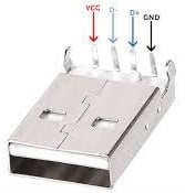
Type-A USB Connector Pin Configuration
The Type A USB pins are designated with coloured wires to carry out various tasks.
- The Type A USB pins are designated with coloured wires to carry out various tasks.
- Type-A USB Connector Pin Configuration
- The coloured wires on the Type A USB pins indicate which functions each pin is intended to perform.
- Pin 1 (VBUS): Power is supplied through this red wire.
- The differential pair pin Pin2 (D-), which is white, is used for USB transmission.
- A differential pair pin in green labelled Pin 3 (D+) is utilised for a USB connection.
- The accessible black Ground pin is designated as Pin 4 (GND).
Both the D+ and D- pins in the aforementioned pins denote the flow of data. The D+ line will flow positively when a “1” is passed across the wires, and negatively when a “0” is sent.
USB Protocol Architecture
The architecture of the USB protocol is shown in the diagram below. After being connected to the computer through USB, various I/O devices all adopt a tree-like topology. In this USB topology, each I/O device will create a point-to-point connection to exchange data utilising the serial transmission protocol.
In this setup, USB connections that resemble hubs are used to connect I/O devices to the computer. The Hub acts as the conduit between the computer and the I/O devices in the architecture. The hosting computer is linked to the entire architecture in this architecture via the root hub. These I/O devices in this design include a keyboard, mouse, speaker, camera, etc.

How Does The USB Protocol Work?
In order to identify whether the input/output device is prepared to transfer data or not, the CPU continuously monitors the USB protocol’s basic functionality, which is based on the polling idea. The I/O devices do not need to inform the processor of their states because the CPU is largely responsible for monitoring continuously. As a result, the USB will be easy and affordable.
A new device connecting to the hub is always given the address “0.” In order to identify the hubs’ state and whether they are attached or detached from the system, the host computer frequently polls them.
The host can then read the data that is present in the new device’s unique memory via its USB port to learn more about the device’s capabilities. a proper driver must be installed on the host for devices to connect with it. A new device is subsequently given an address by the host, which is then recorded in the device register. With this device, USB offers plug-and-play capabilities.
This functionality, to put it simply, enables the host to recognise a new I/O device that becomes available once it is attached. The I/O capabilities of the devices are determined by the host programme.
The “hot-plugging” feature of the USB protocol enables an I/O device to be connected or disconnected from the host system without having to restart the computer. As a result, your system works whether the I/O device is connected or disconnected.
The USB protocol can also enable isochronous traffic, in which data is sent at regular intervals. Isochronous data transmission is substantially quicker than synchronous and asynchronous data transport.
In order to maintain isochronous traffic, the root hub sends a series of bits across USB to specify the start of isochronous data. The actual data can be transmitted after these bits have been transmitted.
USB Protocol Features
- Up to 480 Mbps is the USB 2.0 standard’s top speed.
- A single USB cable can extend up to five metres without a hub and up to 40 metres with one.
- A plug-and-play gadget is a USB.
- It has two options for power: a computer or its own source.
- More than 100 peripherals can be connected with a single USB host controller.
- A USB device can draw up to 5 V and give 500 mA of power.
- Some USBs automatically switch into sleep mode if a computer enters power-saving mode.
- Two wires make up a USB; one wire carries power, while the other one carries data.
- The computer can deliver 500mA of power across the power cables at 5V.
- Low-power devices can get their power directly from the USB.
- A USB can be used to enable two-way communication between the computer and peripheral devices.
USB Standards and Specifications
The specifications of USB will change based on USB standards that include the following.
USB supports three types of speed low speed -1.5 Mbps, Full speed -12 Mbps & High speed – 480 Mbps.
USB 2.0 Standard
- It has a maximum data transfer speed of 480Mbps and is a high-speed USB. All connectors are supported by this USB.
- The cable can be as long as 5 metres.
- It can charge at a maximum of 15w.
USB 3.2 Standard
- A super-fast USB with a 5Gbps maximum data transmission speed is USB 3.2 (Generation 1).
- It is compatible with a variety of USB 3 connectors, including USB-A, USB-B, and USB-C.
- The USB cable’s maximum length is 3 meters.
- It can charge at a maximum of 15w.
USB 3.2 (Generation2)
- A super-fast USB with a 10Gbps maximum data transmission rate is USB 3.2 (Generation 2).
- The USB cord can be as long as 1 metre.
- Additionally, it supports a variety of USB 3 connectors, including USB-A, USB-B, and USB-C.
- It can charge at a maximum of 100w.
USB 3.2 Generation 2×2
- A super-fast USB with a 20Gbps maximum data transmission speed is USB 3.2 Generation 22.
- The USB cord can be as long as 1 metre.
- The USB Connector is also supported.
- It can charge at a maximum of 100w.
Thunderbolt 3 Standard
- Thunderbolt is another name for this USB, which has a maximum data transmission speed of 40Gbps.
- For this USB, the maximum cable length is 2 metres for active cables and 0.8 metres for passive cables.
- It is USB Connector compatible.
- It can charge at a maximum of 100w.
USB 4 Standard
- With a maximum data transfer speed of up to 40Gbps, this USB is also referred to as Thunderbolt 4.
- The maximum cable length for this USB is 2 metres for active cables and 0.8 metres for passive cables.
- It is USB Connector compatible.
- It can charge at a maximum of 100w.
USB Protocol Timing Diagram
The timing diagram for the USB protocol, which is mostly used in engineering to explain the ON/OFF values of USB wires over a timeline, is given below.
A “1” denotes no charge, while a “0” designates active. The evolution of on/off can be seen as time goes on. Non-Return to Zero Invert (NRZI) encoding, is a more effective way to transport data, as demonstrated in the system below.
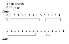
USB Timing Diagram
Bit stuffing is seen in the diagram above, which entails the addition of logic 1s to provide synchronisation. The USB cannot synchronise the data if it contains multiple 1s. In this way, the hardware detects an extra bit and disregards it. It enables reliable transport but also adds overhead to the USB.
USB Data Format
In the USB protocol, master devices sometimes referred to as USB hosts, are those that initiate all communication above the USB bus. In this case, a computer or other controller is typically regarded as the master device; as a result, they only reply to requests for information from other devices. The host device is simply connected to the slave device or peripheral, which is programmed to give the host device the data it needs to function. Keyboards, computer mice, USB flash drives, cameras, and other similar devices are examples of slave or peripheral devices.
The ability of host devices to successfully communicate with one another is crucial. When a peripheral device is connected to a computer through USB, the computer will identify the type of device and automatically load a driver to enable the device to function.
A unit of digital information is exchanged with each packet of the modest quantity of data that is transmitted between the two devices. Below, we discuss how data can be transferred via the USB protocol.
Message Format
The USB protocol transmits data in packets that are LSB first. Token, Data, Handshake, and Start of the Frame are the four primary categories of USB packets. Every packet is made up of different field kinds, which are depicted in the message format diagram below.
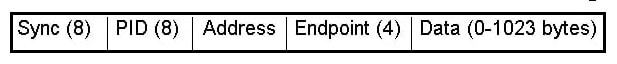
Message Format Diagram of USB
SYNC
Every USB packet will start with a SYNC field in the USB protocol. This field is typically used to properly synchronise the transmitter and receiver for data transmission. A field like SYNC in a slow or fast USB system has 3 KJ pairs, which are followed by 2 Ks to frame 8 bits of data.
To frame 32 bits of data in a Hi-Speed USB system, the synchronisation requires 15 KJ pairs followed by 2 Ks. This field is used to synchronise the CLK of the transmitter and receiver. It is long, with 8 bits for high and low speed and 32 bits for maximum speed. The last two bits will show where the PID field starts.
Packet Identifier Field or PID
The packer identifier field in the USB protocol is primarily used to identify the type of packet being transmitted and, consequently, the format of the packet contents. This field is 8 bits long, with the upper 4 bits identifying the type of packet and the lower 4 bits acting as their bit-wise counterpart.
Address Field
The USB protocol’s address field lets you know which packet device it is primarily intended for. Simply put, 127 devices can be supported by the 7-bit length. The address zero is illegal because packets sent to it should trigger a response from any device that has not yet been assigned an address.
Endpoint Field
The USB protocol’s 4-bit endpoint field provides for more addressing flexibility. These are often split for data travelling in and out. Each device has an endpoint 0, which is a special case called the CONTROL endpoint.
Data Field
The data field can be 0 to 8192 bits long and always contains an integral number of bytes because its length is not defined.
CRC Field
All token packets contain a 5-bit CRC, and all data packets contain a 16-bit CRC, which is used to perform cyclic redundancy checks (CRC) on the data in the packet payload. The start of the frame packet as well as the token packet both use the five-bit CRC-5.
EOP Field
The EOP (End of the Packet) field, which includes an SE0 or single-ended zero for 2-bit times followed by the J for 1-bit times, ends each packet.
Synchronized Issues
The following are some of the typical synchronisation problems with the USB protocol. When creating new USB devices, USB developers frequently run into synchronised problems, also known as USB communication faults. Some of these mistakes will lead to system failures. Some of the problems that can occur with the USB bus are the ones listed below:
- Improper Packet Data & Data Sequencing of USB.
- Transmissions or Retransmissions of USB.
- Power or VBUS-based Issues.
- Troubles through Enumeration.
- High-speed negotiation Problems.
Advantages
- Easy to use.
- For multiple devices, a single interface is used.
- Its size is compact.
- Its connector system is robust.
- These are not expensive.
- These are available in different sizes with different connectors.
- Auto configuration.
- Its expanding is easy.
- High speed.
- Reliable and low cost.
- Power consumption is low.
- Compatible and durable.
Disadvantages
- Some manufacturers create inexpensive, low-quality USBs.
- It has a finite capacity.
- Its data transfer is slower than that of other systems.
- Since USB lacks the broadcasting feature, only the host and peripheral can exchange individual messages.
Applications
- Currently, the majority of peripheral devices, including mice, printers, scanners, joysticks, modems, webcams, keyboards, digital cameras, storage devices, flight yokes, network adapters, and data collecting equipment in the scientific area, are connected to the system via USB.
- Computers typically use hubs and host controllers to use USB.
- Compact devices like mobile phones and USB peripherals like printers are commonly connected via UBB Type-B
- It is most widely used on computers, gaming consoles, and cellphones
Conclusion
I hope all of you have understood the basics of USB Protocol: its Architecture, Working, Synchronisation, DataFormat & Its Applications. We MATHA ELECTRONICS will be back soon with more informative blogs soon.