In the past few years, a variety of communication technologies for IoT device interaction have been available. Bluetooth Module and Wi-Fi Technology are the most common. However, they have a restricted range, few entry points, and considerable power consumption. Semtech, therefore, introduces LoRa technology to resolve these issues. Using a single battery, the device functions for a whole year.

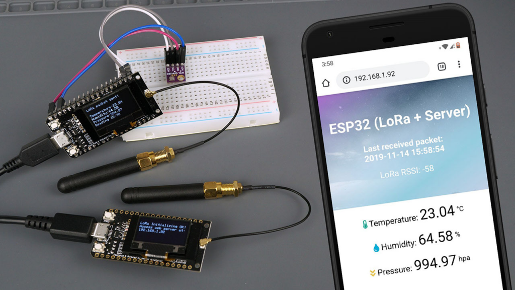
In this IoT project, we will create an ESP32 LoRa Web Server to remotely monitor sensor readings from several kilometers away. Using a DHT11 Sensor, the sender will read humidity and temperature data. The data is then transmitted over LoRa Radio. The data is received by the module containing the OLED Display. This receiver can connect the device to a WiFi network. The IP Address will be displayed on the OLED. Using the IP address, you can connect in to any web browser that monitors sensor readings. Below is a brief summary of the ESP32 LoRa Web Server.
The LoRa receiver operates an asynchronous web server and stores web page files on the ESP32 filesystem (SPIFFS). It also displays the date and time of the most recent readings. The ESP32 utilizes the Network Time Protocol to retrieve data and time.
Bill of Materials
S.N. | COMPONENTS | DESCRIPTION |
1 | ESP32 Board | ESP32 ESP-32S Development Board (ESP-WROOM-32) |
2 | LoRa Module | SX1278/76 Lora Module |
3 | OLED Display | 0.96″ I2C OLED Display |
4 | Connecting Wires | Jumper Wires |
5 | Breadboard | – |
6 | DHT11 Sensor | DHT11 Humidity Temperature Sensor |
Installing the Required Libraries
Several Libraries are required for the Arduino IDE project to program the ESP32 Board.
1. DHT11 Library
Temperature and humidity readings require a temperature and humidity sensor. DHT11 is the best and cheapest sensor for this purpose. This requires the installation of the DHT11 Library. Download the library from the link below and import it into the Arduino IDE.
2. LoRa Library
We require an Arduino library for data transmission and reception utilising LoRa radios. The library supports modules such as Semtech SX1276, SX1277, SX1278, and SX1279, as well as HopeRF RFM95W, RFM96, and RFM98W.
3. OLED Libraries
We need two OLED Display Libraries. Adafruit SSD1306 is a library based on SSD1306 drivers for our Monochrome OLEDs. The Adafruit GFX Library is the primary graphics library for all of our displays, offering a standard set of graphics primitives (points, lines, circles, etc.).
Download SSD1306 Library & Download Adafruit GFX Library
4. NTPClient Library
Network Time Protocol (NTP) is a networking protocol for synchronizing clocks across packet-switched, variable-latency data networks. When the LoRa receiver receives a new LoRa message, it will request the date and time from an NTP server in order to determine when the last packet was received.
5. Asynchronous Web Server Libraries
To create an asynchronous web server, two libraries are required: the ESPAsyncWebServer library and the Async TCP Library.
Download ESPAsyncWebServer Library & Download AsyncTCP Library
Installing ESP32 Filesystem Uploader Plugin
SPIFFS
SPIFFS enables access to the flash memory in a manner similar to that of a standard filesystem on a computer, albeit with fewer features and restrictions. SPIFFS with the ESP32 board is particularly beneficial for:
1.Create settings configuration files
2. Save data permanently
3. Instead of storing modest quantities of data on a microSD card, create files.
4. Save HTML and CSS files in order to create a web server
5. Save pictures, illustrations, and symbols
This project involves uploading a webpage and an image to the ESP32 File System.
Installing the Arduino ESP32 Filesystem Uploader
To install the filesystem uploader, please follow these steps:
Step 1: Visit the link: Release for esptool_py. From here download the ESP32FS-1.0.zip
Step 2: Extract the folder ESP32FS-1.0.zip
Step 3: Move the ESP32FS folder to the C:Program Files (x86)Arduinotools directory.
Step 4: Restart the Arduino integrated development environment. Click on tools to access the “Upload Sketch Data” option.
You have now installed the SPIFFS plugin successfully. The remaining items must be completed on the receiver sketch below.
Circuit: ESP32 LoRa Sensor Data Monitoring on Web Server
Let’s now examine the sender and receiver circuits for the ESP32 LoRa Web Server. I constructed both circuits on breadboard. You may use PCB if you so like.
Sender Circuit for ESP32 LoRa Web Server
The following is an ESP32 LoRa Module SX1278 Sender Circuit with a DHT11 Sensor. This component serves as a transmitter. DHT11 Humidity Temperature Sensor reads and transmits humidity and temperature data through LoRa Radio.
The connection is fairly simple. Simlarly connect the Lora SX1278 & ESP32 as follows.
ESP32 PINS | SX1278 PINS |
GND | GND |
3.3V | VCC |
D5 | NSS |
D23 | MOSI |
D19 | MISO |
D18 | SCK |
D14 | RST |
D2 | DIO0 |
Connect similarly the DHT11 digital input pin to GPIO4 on the ESP32. Connect its VCC to ESP32’s 3.3V and GND to its GND.
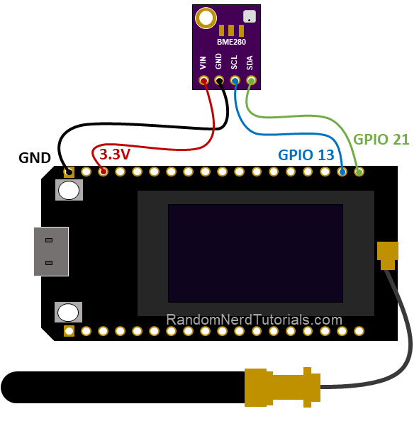
Receiver Circuit for ESP32 LoRa Web Server
The following is an ESP32 LoRa Module SX1278 Receiver Circuit with an OLED Display. This component serves as a Receiver. Using LoRa Radio, humidity and temperature data are received.
The ESP32 and LoRa SX1278 connection is the same as described previously. However, the OLED must be linked here. Connect the I2C pins of the OLED display, SDA and SCL, to GPIO21 and GPIO22 on the ESP32. Provide 3.3V VCC and connect the GND to GND.
ESP32 LoRa Sender Code
After assembling the Sender Circuit circuit on breadboard. Copy and upload the following code to the ESP32 Board. Before uploading, be sure to adjust the LoRa frequency to match the region.
#define BAND 433E6 //433E6 for Asia, 866E6 for Europe, 915E6 for North America |
//Libraries for LoRa #include <SPI.h> #include <LoRa.h> //Libraries for LoRa #include “DHT.h” #define DHTPIN 4 //pin where the dht11 is connected DHT dht(DHTPIN, DHT11); //define the pins used by the LoRa transceiver module #define ss 5 #define rst 14 #define dio0 2 #define BAND 433E6 //433E6 for Asia, 866E6 for Europe, 915E6 for North America //packet counter int readingID = 0; int counter = 0; String LoRaMessage = “”; float temperature = 0; float humidity = 0; //Initialize LoRa module void startLoRA() { LoRa.setPins(ss, rst, dio0); //setup LoRa transceiver module while (!LoRa.begin(BAND) && counter < 10) { Serial.print(“.”); counter++; delay(500); } if (counter == 10) { // Increment readingID on every new reading readingID++; Serial.println(“Starting LoRa failed!”); } Serial.println(“LoRa Initialization OK!”); delay(2000); } void startDHT() { if (isnan(humidity) || isnan(temperature)) { Serial.println(“Failed to read from DHT sensor!”); return; } } void getReadings(){ humidity = dht.readHumidity(); temperature = dht.readTemperature(); Serial.print(F(“Humidity: “)); Serial.print(humidity); Serial.print(F(“% Temperature: “)); Serial.print(temperature); Serial.println(F(“°C “)); } void sendReadings() { LoRaMessage = String(readingID) + “/” + String(temperature) + “&” + String(humidity) ; //Send LoRa packet to receiver LoRa.beginPacket(); LoRa.print(LoRaMessage); LoRa.endPacket(); Serial.print(“Sending packet: “); Serial.println(readingID); readingID++; Serial.println(LoRaMessage); } void setup() { //initialize Serial Monitor Serial.begin(115200); dht.begin(); startDHT(); startLoRA(); } void loop() { getReadings(); sendReadings(); delay(5000); } |
ESP32 LoRa Web Server Receiver Code
The LoRa Receiver receives incoming LoRa packets and transmits the data to an asynchronous web server. In addition to the sensor readings, the last time these measurements were obtained and the RSSI are also displayed (received signal strength indicator).
Along with the HTML file, we must save the image on the ESP32 filesystem (SPIFFS).
Creating index.html webpage
The following code should be copied and pasted into Notepad. Save the file as index.html in order to publish the final webpage.
<!DOCTYPE HTML><html> <head> <meta name=”viewport” content=”width=device-width, initial-scale=1″> <link rel=”icon” href=”data:,”> <title>ESP32 (LoRa + Server)</title> <link rel=”stylesheet” href=”https://use.fontawesome.com/releases/v5.7.2/css/all.css” integrity=”sha384-fnmOCqbTlWIlj8LyTjo7mOUStjsKC4pOpQbqyi7RrhN7udi9RwhKkMHpvLbHG9Sr” crossorigin=”anonymous”> <style> body { margin: 0; font-family: Arial, Helvetica, sans-serif; text-align: center; } header { margin: 0; padding-top: 5vh; padding-bottom: 5vh; overflow: hidden; background-image: url(mainimage); background-size: cover; color: white; } h2 { font-size: 2.0rem; } p { font-size: 1.2rem; } .units { font-size: 1.2rem; } .readings { font-size: 2.0rem; } </style> </head> <body> <header> <h2>ESP32 (LoRa + Server)</h2> <p><strong>Last received packet:<br/><span id=”timestamp”>%TIMESTAMP%</span></strong></p> <p>LoRa RSSI: <span id=”rssi”>%RSSI%</span></p> </header> <main> <p> <i class=”fas fa-thermometer-half” style=”color:#059e8a;”></i> Temperature: <span id=”temperature” class=”readings”>%TEMPERATURE%</span> <sup>°C</sup> </p> <p> <i class=”fas fa-tint” style=”color:#00add6;”></i> Humidity: <span id=”humidity” class=”readings”>%HUMIDITY%</span> <sup>%</sup> </p> </main> <script> setInterval(updateValues, 10000, “temperature”); setInterval(updateValues, 10000, “humidity”); setInterval(updateValues, 10000, “rssi”); setInterval(updateValues, 10000, “timestamp”); function updateValues(value) { var xhttp = new XMLHttpRequest(); xhttp.onreadystatechange = function() { if (this.readyState == 4 && this.status == 200) { document.getElementById(value).innerHTML = this.responseText; } }; xhttp.open(“GET”, “/” + value, true); xhttp.send(); } </script> </body> </html> |
Creating data folder & its content
Create the folder data and place the index.html file inside of it. Additionally, download and place this image in the same folder. The image should retain the name mainimage. You may use any image you choose, but the filename must remain the same.
Now copy the data folder and paste it together with the ino file into the sketh folder of the receiver.
Uploading html & image to SPIFFS
After completing the preceding procedures, you can now upload the file system:
LoRa Receiver Code
After uploading the HTML page and image to SPIFFS, you can copy the code below and upload the ESP32 Board’s receiver code. Change WiFi SSID and password in the code provided below.
const char* ssid = “Alexahome”; const char* password = “12345678”; |
// Import Wi-Fi library #include <WiFi.h> #include “ESPAsyncWebServer.h” #include <SPIFFS.h> //Libraries for LoRa #include <SPI.h> #include <LoRa.h> //Libraries for OLED Display #include <Wire.h> #include <Adafruit_GFX.h> #include <Adafruit_SSD1306.h> // Libraries to get time from NTP Server #include <NTPClient.h> #include <WiFiUdp.h> //define the pins used by the LoRa transceiver module #define ss 5 #define rst 14 #define dio0 2 #define BAND 433E6 //433E6 for Asia, 866E6 for Europe, 915E6 for North America //OLED pins #define OLED_SDA 21 #define OLED_SCL 22 #define OLED_RST -1 #define SCREEN_WIDTH 128 // OLED display width, in pixels #define SCREEN_HEIGHT 64 // OLED display height, in pixels // Replace with your network credentials const char* ssid = “Alexahome”; const char* password = “12345678”; // Define NTP Client to get time WiFiUDP ntpUDP; NTPClient timeClient(ntpUDP); // Variables to save date and time String formattedDate; String day; String hour; String timestamp; // Initialize variables to get and save LoRa data int rssi; String loRaMessage; String temperature; String humidity; String readingID; // Create AsyncWebServer object on port 80 AsyncWebServer server(80); Adafruit_SSD1306 display(SCREEN_WIDTH, SCREEN_HEIGHT, &Wire, OLED_RST); // Replaces placeholder with DHT values String processor(const String& var){ //Serial.println(var); if(var == “TEMPERATURE”){ return temperature; } else if(var == “HUMIDITY”){ return humidity; } else if(var == “TIMESTAMP”){ return timestamp; } else if (var == “RRSI”){ return String(rssi); } return String(); } //Initialize OLED display void startOLED(){ //reset OLED display via software pinMode(OLED_RST, OUTPUT); digitalWrite(OLED_RST, LOW); delay(20); digitalWrite(OLED_RST, HIGH); //initialize OLED Wire.begin(OLED_SDA, OLED_SCL); if(!display.begin(SSD1306_SWITCHCAPVCC, 0x3c, false, false)) { // Address 0x3C for 128×32 Serial.println(F(“SSD1306 allocation failed”)); for(;;); // Don’t proceed, loop forever } display.clearDisplay(); display.setTextColor(WHITE); display.setTextSize(1); display.setCursor(0,0); display.print(“LORA SENDER”); } //Initialize LoRa module void startLoRA(){ int counter; //setup LoRa transceiver module LoRa.setPins(ss, rst, dio0); //setup LoRa transceiver module while (!LoRa.begin(BAND) && counter < 10) { Serial.print(“.”); counter++; delay(500); } if (counter == 10) { // Increment readingID on every new reading Serial.println(“Starting LoRa failed!”); } Serial.println(“LoRa Initialization OK!”); display.setCursor(0,10); display.clearDisplay(); display.print(“LoRa Initializing OK!”); display.display(); delay(2000); } void connectWiFi(){ // Connect to Wi-Fi network with SSID and password Serial.print(“Connecting to “); Serial.println(ssid); WiFi.begin(ssid, password); while (WiFi.status() != WL_CONNECTED) { delay(500); Serial.print(“.”); } // Print local IP address and start web server Serial.println(“”); Serial.println(“WiFi connected.”); Serial.println(“IP address: “); Serial.println(WiFi.localIP()); display.setCursor(0,20); display.print(“Access web server at: “); display.setCursor(0,30); display.print(WiFi.localIP()); display.display(); } // Read LoRa packet and get the sensor readings void getLoRaData() { Serial.print(“Lora packet received: “); // Read packet while (LoRa.available()) { String LoRaData = LoRa.readString(); // LoRaData format: readingID/temperature&soilMoisture#batterylevel // String example: 1/27.43&654#95.34 Serial.print(LoRaData); // Get readingID, temperature and moisture int pos1 = LoRaData.indexOf(‘/’); int pos2 = LoRaData.indexOf(‘&’); readingID = LoRaData.substring(0, pos1); temperature = LoRaData.substring(pos1 +1, pos2); humidity = LoRaData.substring(pos2+1, LoRaData.length()); } // Get RSSI rssi = LoRa.packetRssi(); Serial.print(” with RSSI “); Serial.println(rssi); } // Function to get date and time from NTPClient void getTimeStamp() { while(!timeClient.update()) { timeClient.forceUpdate(); } // The formattedDate comes with the following format: // 2018-05-28T16:00:13Z // We need to extract date and time formattedDate = timeClient.getFormattedDate(); Serial.println(formattedDate); // Extract date int splitT = formattedDate.indexOf(“T”); day = formattedDate.substring(0, splitT); Serial.println(day); // Extract time hour = formattedDate.substring(splitT+1, formattedDate.length()-1); Serial.println(hour); timestamp = day + ” ” + hour; } void setup() { // Initialize Serial Monitor Serial.begin(115200); startOLED(); startLoRA(); connectWiFi(); if(!SPIFFS.begin()){ Serial.println(“An Error has occurred while mounting SPIFFS”); return; } // Route for root / web page server.on(“/”, HTTP_GET, [](AsyncWebServerRequest *request){ request->send(SPIFFS, “/index.html”, String(), false, processor); }); server.on(“/temperature”, HTTP_GET, [](AsyncWebServerRequest *request){ request->send_P(200, “text/plain”, temperature.c_str()); }); server.on(“/humidity”, HTTP_GET, [](AsyncWebServerRequest *request){ request->send_P(200, “text/plain”, humidity.c_str()); }); server.on(“/timestamp”, HTTP_GET, [](AsyncWebServerRequest *request){ request->send_P(200, “text/plain”, timestamp.c_str()); }); server.on(“/rssi”, HTTP_GET, [](AsyncWebServerRequest *request){ request->send_P(200, “text/plain”, String(rssi).c_str()); }); server.on(“/mainimage”, HTTP_GET, [](AsyncWebServerRequest *request){ request->send(SPIFFS, “/mainimage.jpg”, “image/jpg”); }); // Start server server.begin(); // Initialize a NTPClient to get time timeClient.begin(); // Set offset time in seconds to adjust for your timezone, for example: // GMT +1 = 3600 // GMT +8 = 28800 // GMT -1 = -3600 // GMT 0 = 0 timeClient.setTimeOffset(0); } void loop() { // Check if there are LoRa packets available int packetSize = LoRa.parsePacket(); if (packetSize) { getLoRaData(); getTimeStamp(); } } |
Testing the Sender & Receiver with ESP32 LoRa Web Server
Once the code has been uploaded, the Serial Monitor can be accessed to observe the following results for transmitting and receiving.
On the receiving end, the OLED display is visible. The IP Address is displayed on the OLED display.
Access any web browser on a computer or mobile device. The IP address displayed on the OLED display should be visited. You can watch a beautiful representation of LoRa Received messages on the Webserver. In addition to the RSSI value, temperature and humidity data are displayed. Additionally, the homepage displays the time of the last received packet.
Conclusion
Hope this blog helps you to understand how to design an ESP32 LoRa Sensor Data Monitoring on a Web Server. We, MATHA ELECTRONICS will come back with more informative blogs.