
We will learn about NodeMCU, the ESP-12E Module, the NodeMCU board layout, a quick pinout, and how to programme NodeMCU with the Arduino IDE in this lesson. This is a comprehensive introduction to using the NodeMCU ESP-12E Board. So let’s get started.
A Brief Lookback at ESP8266
The ESP8266 has had an overwhelmingly positive impact on the hobbyist and DIY communities, particularly in the creation of IoT (Internet of Things)-related applications. Espressif Systems created the ESP8266 SoC, a low-cost Wi-Fi microcontroller with a full TCP/IP stack.
What is NodeMCU?
Technically speaking, NodeMCU is ESP8266 firmware created with Espressif NON-OS SDK, C programming language, and Lua scripting language.
Traditionally, we write our code in C or C++ and compile it using a collection of tools to create a binary file for our microcontrollers, such as Arduino, STM32, 8051, and others. The microcontroller’s flash memory is then used to run the binary file that was previously uploaded there.
With NodeMCU, things are significantly different. You can think of the NodeMCU firmware as a Lua Script interpreter. Therefore, you can easily create your application in Lua and send it to the ESP8266 if your ESP8266 is running the NodeMCU Firmware.
The commands are translated into bytecode and carried out by the NodeMCU Firmware. There is no binary file, compilation, etc. Simply create a script and execute it.
The NodeMCU Devkit is a breakout board for the ESP-12E module created by the same team that created the NodeMCU Firmware. As a result, many of us use the NodeMCU board and programme it using the Arduino IDE rather than Lua Scripts.
Important Information: The ESP8266 can support just one firmware. It could be Arduino-based code, AT Commands firmware, or NodeMCU firmware. The NodeMCU firmware is deleted after an Arduino sketch is uploaded. You must flash the NodeMCU Firmware in order to use Lua scripts with NodeMCU.
ESP-01 vs. NodeMCU (ESP-12E)
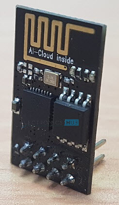
The NodeMCU Devkit is, as was already said, a Breakout Board for the ESP-12E Module. The ESP-01 is a third-party module manufacturer for the ESP8266 Wi-Fi SoC and is made by Ai-Thinker.

Pinout of ESP-01 Module
In fact, Ai-modules Thinker’s are among those that are frequently found in other ESP8266 boards. Ai-Thinker offers modules with names like ESP-01, ESP-02, ESP-03, and so on all the way up to ESP-14.
NOTE: The ESP8266 Wi-Fi Chip serves as the foundation for all modules. The availability of GPIO Pins is the primary distinction. For instance, whereas the ESP-12E Module contains 17 GPIO Pins, an ADC Pin, SPI Pins, and other pins, the ESP-01 Module only has 2 GPIO Pins.
The ESP-12E is the most well-liked of all of these modules. The NodeMCU team created the NodeMCU Devkit, also known as the NodeMCU Board, using this module as its primary board.
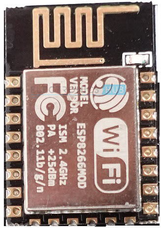
ESP-12E Module with edge castellations
If you recall from the “Getting Started with ESP8266” course, the ESP-01 Module required a lot of work to programme. To transition between Programming mode (GPIO 0 must be connected to GND) and Normal Operation Mode, it requires a USB to UART Module and a few push buttons (GPIO 0 can be left floating or can be pulled high to 3.3V).
This is all made simpler with the NodeMCU board. First off, there are numerous GPIO Pins because it is based on the ESP-12E Module. Second, a 3.3V regulator is built inside the device (remember, the ESP8266EX SoC works on 3.3V and not on 5V).
One more wonderful feature of NodeMCU is the on-board USB to UART Controller, or CP2102 IC in my instance. The GPIO 0 and RST pins of the ESP8266 SoC are controlled by the DTR (Data Terminal Ready) and RTS (Request to Send) pins of the CP2102 IC, which is an intriguing feature of the device.
Therefore, the CP2102 IC automatically selects the Programming mode and resets the board whenever you attempt to upload any sketch from the Arduino IDE. Once the programming is complete, the ESP8266 is configured to return to Normal Running mode. Beautiful.
The official github page of NodeMCU is here.
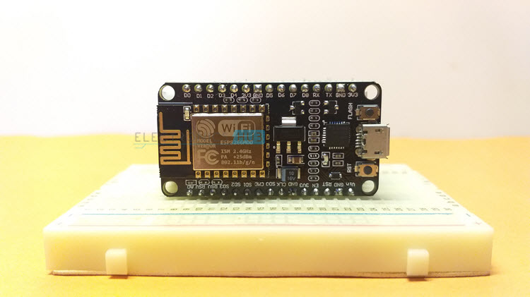
Layout of NodeMCU ESP-12E Breakout Board
The layout of NodeMCU Board, a breakout board based on the ESP-12E Module, is shown in the next figure. Edge castellations on the ESP-12E Module make it simple to solder to a PCB.
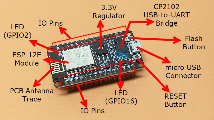
Layout of NodeMCU Board
The ESP-12E Module with PCB Antenna, CP2102 USB to UART Bridge Controller from Silicon Labs, two push buttons (one is RESET and the other is Flash), a micro-USB Connector for Power and Uploading, a 3.3V Regulator, some passive and active components, and two LEDS are all included on the NodeMCU board, as you can see in the image.
Yes. There are two LEDs included into the NodeMCU. The first LED is attached to GPIO 2 of the ESP8266 SoC and is included with the ESP-12E Module. The second LED is attached to GPIO 16 and is located on the break-out board close to the CP2102 IC.

Two on-board LEDs on NodeMCU
NOTE: Because both LEDs are active LOW, they both light up when the pins are low and turn off when the pins are high.
Pinout
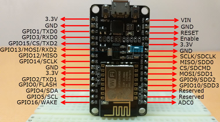
I’ll quickly run through the NodeMCU ESP-12E Breakout board’s pinout. I will go over the whole pinout of the NodeMCU Board, the ESP-12E Module, the pin description, and other key aspects in a separate tutorial.
The pinout of the NodeMCU Board is displayed in the figure below.
How to Program NodeMCU using Arduino IDE?
You must upload the Blinky Sketch using the Arduino IDE in order to finish the Getting Started with NodeMCU tutorial. So let’s start configuring the Arduino IDE. You likely finished the initial setup in the Arduino IDE if you worked with the ESP-01 Module or other ESP8266-based boards.
Preparing Arduino IDE
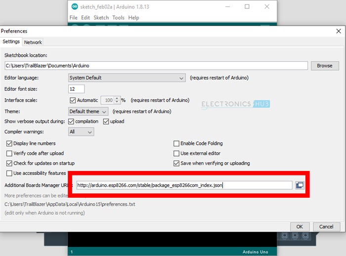
But yet, allow me to recapitulate the stages. Go to File -> Preferences in the Arduino IDE after opening it (if it isn’t already installed, you should install it first).
At the bottom, there is a section labelled “Additional Boards Manager URLs:”. Copy and paste the URL below into the box next to this.
.
| http://arduino.esp8266.com/stable/package_esp8266com_index.json |
If you want to add multiple URLs, then simply separate them by comma.
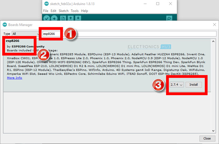
This enables the Arduino IDE to search the internet for more boards. Therefore, confirm that your system is online. After that, select the Boards Manager option under Tools -> Board.
Look up “esp8266” using the search bar at the top. You will see “esp8266 by ESP8266 Community” as the result. Select it, then choose Install. All of the tools, libraries, and boards will be downloaded.
Search and Install ESP8266
You can begin writing code for your new NodeMCU board once you have installed the ESP8266 boards. First, insert one end of the micro-USB cable into the NodeMCU and the other end into the PC.
Go back to the Arduino IDE’s Tools -> Board -> ESP8266 Boards menu and choose “NodeMCU 1.0 ESP-12E Module.”

Select NodeMCU in Arduino Boards
All board-related parameters in the IDE are altered to be particular to the ESP8266 NodeMCU when you select the Tools option. Except for the Port, leave all the parameters at their default values. For the USB to UART Controller, choose the proper port. You may find this information in Windows’ “Device Manager.”

ptions specific to NodeMCU
Testing with Blinky Sketch
Two internal LEDs on the NodeMCU are linked to GPIO 2 and GPIO 16, as I already indicated. Therefore, I’ll alternately flash both LEDs in this Blinky Sketch example for NodeMCU.
The code for Blinking LEDs on NodeMCU is given below.
| #define ledPin1 2 /* LED connected to GPIO 2 */ | |
| #define ledPin2 16 /* LED connected to GPIO 16 */ | |
| void setup() | |
| { | |
| pinMode(ledPin1, OUTPUT); | |
| pinMode(ledPin2, OUTPUT); | |
| } | |
| void loop() | |
| { | |
| digitalWrite(ledPin1, LOW); | |
| digitalWrite(ledPin2, HIGH); | |
| delay(1000); | |
| digitalWrite(ledPin1, HIGH); | |
| digitalWrite(ledPin2, LOW); | |
| delay(1000); | |
| } |
view rawNodeMCU-Blinky.ino hosted with ❤ by GitHub
The Arduino IDE will launch several ESP8266-related tools to compile the code and create the binary file as soon as you click the Upload button.
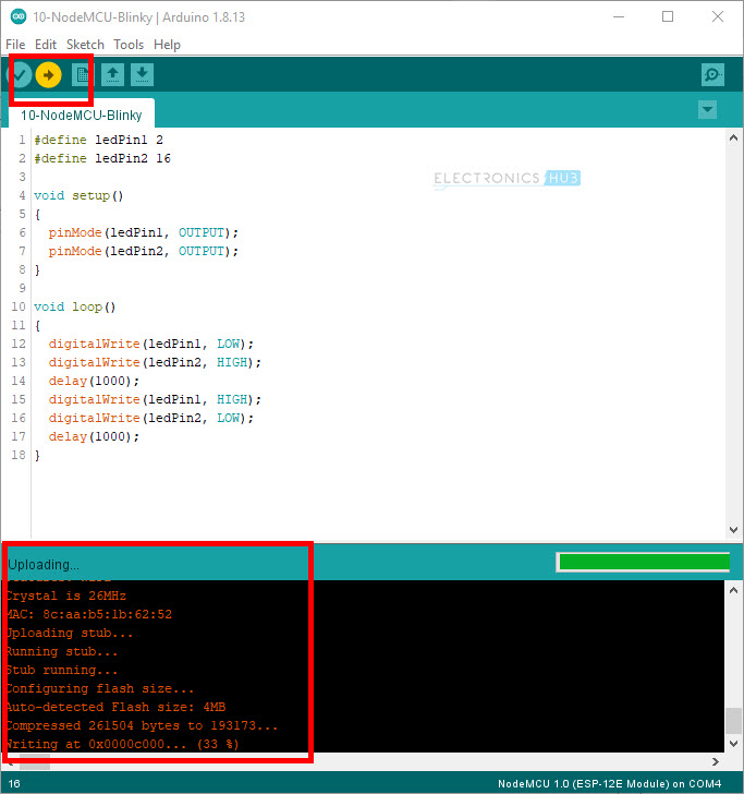
Following is short video snippet of the output.
Conclusion
I hope all of you had understand the basics of how to get started with NodeMCU. We MATHA ELECTRONICS will be back soon with more informative blogs soon.