
How to Interface PCF8574 I2C LCD with ESP8266 NodeMCU?

In this article, we’ll see how to connect an ESP8266 NodeMCU Development Board to an I2C LCD. A unique module for 162 and 204 Character LCD Displays is the PCF8574 I2C LCD. We will discover how the I2C LCD interface on the ESP8266 NodeMCU functions, how to configure I2C in the NodeMCU, and how to show some data on the 162 LCD.

Need for I2C LCD
A great development board for Wi-Fi-related applications is the ESP8266 NodeMCU. The GPIO Pins on this board provide an additional benefit. There are around 9 GPIO pins left over after all the dedicated ones (for the SPI Flash IC and UART) have been removed.
But what if you want to connect an ESP8266 NodeMCU to a 162 character LCD display? The 162 LCD will use 6 GPIO Pins of the microcontroller even in 4-bit Parallel connection mode (four for Data, one for RS and one for E).
If you want to connect additional significant sensors and devices, using that many GPIO Pins for a character LCD Display is not practical.
The I2C LCD Module comes in handy in this situation. It connects via the I2C interface and is specifically built for 16- and 20-character LCD displays. As a result, we are now down to two GPIO Pins from six previously (SDA and SCL of I2C).
A Quick Overview of the PCF8574 I2C LCD Module
The PCF8574 I2C LCD Module is based on the PCF8574 GPIO Expander IC, as the name would imply. It was initially used in modules to increase a microcontroller’s GPIO pins, and it interacted with the microcontroller via the I2C interface.

The I2C LCD Module is specifically designed to drive a character LCD rather than GPIO extension. Therefore, it has a pinout that is similar to a conventional 162 LCD, a potentiometer for adjusting contrast, and a jumper for turning on or off the backlight.

ESP8266 NodeMCU I2C LCD
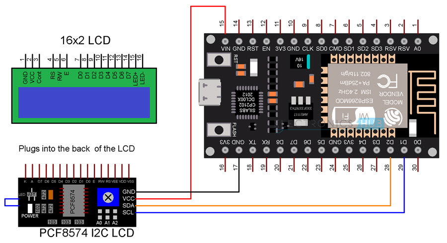
Now let’s examine the operation of the ESP8266 NodeMCU I2C LCD Interface. D1 and D2, which correspond to GPIO 5 and GPIO 4, are typically utilised for I2C communication if you recall the ESP8266 NodeMCU’s wiring.
SCL pin is D1 (GPIO 5) while SDA pin is D2 (GPIO 4). These two pins are required to connect to the PCF8574 I2C LCD Module.
The I2C LCD Module merely connects into the pins of the LCD Display; there are no other connections between the Module and the LCD Display itself. Only the supply and I2C connections are required.

The connections between the ESP8266 NodeMCU and the I2C LCD Module are displayed in the following table.
| I2C LCD Module | ESP8266 NodeMCU |
| GND | GND |
| VCC | VIN |
| SDA | D2 – GPIO 4 |
| SCL | D1 – GPIO 5 |
NOTE: The LCD Display requires a supply voltage of 4.7 to 5.3 volts to operate. In other words, we are providing 5V from the NodeMCU instead of 3.3V from the PCF8574 IC, which operates at a 2.5 V to 6 V supply.
Components Required
- ESP8266 NodeMCU
- PCF8574 I2C LCD Module
- 16×2 Character LCD Display
- Breadboard
- Connecting Wires
Circuit Diagram
You must download a specific library if you haven’t used an I2C LCD Module previously. Navigate to Tools -> Manage Libraries in the open Arduino IDE window.
Download the “LiquidCrystal I2C” library created by Frank de Brabander by searching for “liquidcrystal i2c.”
Preparing Arduino IDE
You must download a specific library if you haven’t used an I2C LCD Module previously. Navigate to Tools -> Manage Libraries in the open Arduino IDE window.
Download the “LiquidCrystal I2C” library created by Frank de Brabander by searching for “liquidcrystal i2c.”

This library was utilised in a few of my earlier projects. Therefore, as you can see, it has already been installed for me.
Connect the ESP8266 NodeMCU to the computer by making the previously specified connections. Ensure that NodeMCU is chosen in the boards and that the appropriate COM Port is configured.

Getting the Slave Address of I2C LCD Module
We must first identify the Slave Address of the PCF8574 I2C LCD Module before writing the real code to display things on the LCD. If you recall the fundamentals of I2C communication, a master can only speak to a slave if it is aware of the slave address.
The I2C Bus master in this instance is the ESP8266 NodeMCU, while the I2C LCD Module PCF8574 is the slave.
So let’s use the following code to find the I2C LCD module’s slave address. After completing all of the connections, launch the serial monitor and upload the code to the ESP8266 NodeMCU.
Code
| #include <Wire.h> | |
| void setup() | |
| { | |
| Wire.begin(); | |
| Serial.begin(115200); | |
| while (!Serial); | |
| } | |
| void loop() | |
| { | |
| byte error, address; | |
| int I2CDevices; | |
| Serial.println(“Scanning for I2C Devices…”); | |
| I2CDevices = 0; | |
| for (address = 1; address < 127; address++ ) | |
| { | |
| Wire.beginTransmission(address); | |
| error = Wire.endTransmission(); | |
| if (error == 0) | |
| { | |
| Serial.print(“I2C device found at address 0x”); | |
| if (address < 16) | |
| { | |
| Serial.print(“0”); | |
| } | |
| Serial.print(address, HEX); | |
| Serial.println(” !”); | |
| I2CDevices++; | |
| } | |
| else if (error == 4) | |
| { | |
| Serial.print(“Unknown error at address 0x”); | |
| if (address < 16) | |
| { | |
| Serial.print(“0”); | |
| } | |
| Serial.println(address, HEX); | |
| } | |
| } | |
| if (I2CDevices == 0) | |
| { | |
| Serial.println(“No I2C devices found\n”); | |
| } | |
| else | |
| { | |
| Serial.println(“****\n”); | |
| } | |
| delay(5000); | |
| } |
If a slave acknowledges, the ESP8266 will search for it, obtain its slave address, and print it on the serial monitor. In my example, the slave address is 0x3F, and the main code must use this slave address.

Displaying Simple Text
Now, let’s look at how to use the ESP8266 and I2C LCD Module to display a straightforward text on the 162 LCD. There are no further connections because the ones that have already been formed suffice.
Code
| #include <Wire.h> | |
| #include <LiquidCrystal_I2C.h> | |
| LiquidCrystal_I2C lcd(0x3F, 16, 2); | |
| void setup() | |
| { | |
| lcd.init(); | |
| lcd.backlight(); | |
| lcd.setCursor(0,0); | |
| lcd.print(” I2C LCD with “); | |
| lcd.setCursor(0,1); | |
| lcd.print(“ESP8266 NodeMCU”); | |
| } | |
| void loop() | |
| { | |
| } |

ADC Value on LCD
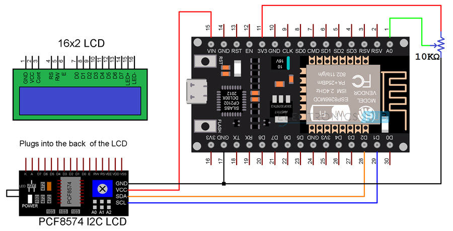
In addition, I created a tiny circuit that connects a 10 K potentiometer to the NodeMCU’s ADC pins (labelled A0) and uses an I2C LCD Module to display the ADC result on the LCD.
If you recall the ESP8266’s specifications, its inbuilt ADC has a 10-bit resolution. The ADC will therefore provide a value between 0 and 1023 as its output.
Keep in mind that the ESP8266 only has one ADC Channel. The ADC Pin is identified on the NodeMCU board as pin A0. The NodeMCU’s A0 is wired to the wiper pin of the 10 K potentiometer. The potentiometer’s additional two pins are wired to 3.3V and GND, respectively.
NOTE: Only connect the POT to 3.3V. The POT should not be connected to 5V because the ESP8266 ADC can only withstand 3.3V.
Circuit Diagram
The circuit diagram for connecting a 10 K potentiometer to an ESP8266 NodeMCU and showing the ADC result on an I2C LCD is shown in the accompanying image.
Code
| #include <Wire.h> | |
| #include <LiquidCrystal_I2C.h> | |
| #define analogPin A0 /* ESP8266 Analog Pin ADC0 = A0 */ | |
| int adcValue = 0; /* Variable to store Output of ADC */ | |
| LiquidCrystal_I2C lcd(0x3F, 16, 2); | |
| void setup() | |
| { | |
| lcd.init(); | |
| lcd.backlight(); | |
| lcd.setCursor(0,0); | |
| lcd.print(“ADC Value = “); | |
| } | |
| void loop() | |
| { | |
| adcValue = analogRead(analogPin); /* Read the Analog Input value */ | |
| lcd.setCursor(0,0); | |
| lcd.print(“ADC Value = “); | |
| lcd.setCursor(12, 0); | |
| lcd.print(adcValue); | |
| delay(1000); | |
| } |

Conclusion
I hope all of you had understand the basics of interfacing PCF8574 I2C LCD Module with ESP8266 NodeMCU Development Board. We MATHA ELECTRONICS will be back soon with more informatice blogs soon.