
How to Configure GPIO Pins as ESP8266 NodeMCU Input-Output?
In this tutorial, we’ll go over some fundamental ESP8266 digital input and output operations. I decided to use a push button as a digital input device and an LED as a digital output device to demonstrate ESP8266 NodeMCU Input Output operations on the NodeMCU board.

Introduction
This simple tutorial will show you how to set up the GPIO pins on the ESP8266 NodeMCU board as digital input and output.

NodeMCU (ESP-12E) Board
You should read the “Getting Started with NodeMCU” and “NodeMCU Pinout” tutorials before continuing with this one.
I covered how to set up the Arduino IDE for programming the NodeMCU board in the Getting Started with NodeMCU tutorial. Setting up your Arduino IDE correctly is a crucial step that only needs to be done once, after which you may relax.
ESP8266 NodeMCU Input Output Operations
You would notice that not all of the GPIO Pins on the NodeMCU Board can be utilised as straightforward GPIO Pins for Digital Input and Output operations if you glanced at the ESP8266 NodeMCU Pinout.
There are 17 GPIO Pins, but 8 of them are already in use for other tasks like UART and SPI Flash. So, 9 GPIO Pins are all that are left. Even in those 9, some of them are used during the boot up process while others are in a default condition.

Therefore, choosing the appropriate GPIO Pins requires great consideration. For instance, if you use a GPIO pin to drive a relay and it is in the HIGH state at startup, the relay will turn on when the computer boots up. Not all applications may benefit from this circumstance.
For this project’s demonstration, I used NodeMCU’s GPIO4 and GPIO5, or D2 and D1, as a safety measure. These pins can be used without restriction and have no additional uses.
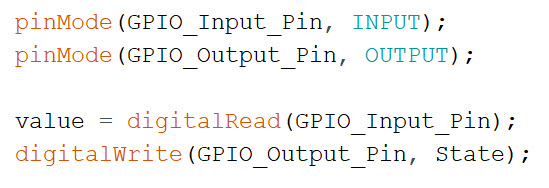
You must use the pinMode() function to set a GPIO pin to be either an input or an output. Once the pins are configured, you can use the digitalRead() method to read from an input pin and the digitalWrite() function to write to an output pin.
Components Required
- ESP8266 NodeMCU
- 5mm LED
- Micro USB Cable
- 330 Ω Resistor
- 10 KΩ Resistor
- Push Button
- Breadboard
- Breadboard Power Supply (optional)
- Connecting Wires
Circuit Diagram
The circuit diagram for the ESP8266 NodeMCU Input Output Operations example is displayed in the following image.

Code
Below is a list of the project’s code. No extra libraries need to be downloaded.
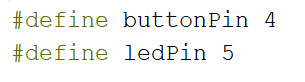
| #define buttonPin 4 /* GPIO4 (D2) for Push Button */ | |
| #define ledPin 5 /* GPIO5 (D1) for LED */ | |
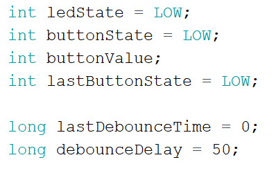
| int ledState = LOW; /* Variable to hold the current state of LED Pin. Initialized to LOW */ | |
| int buttonState = LOW; /* Variable to hold current state of Button Pin. Initialized to LOW */ | |
| int buttonValue; /* Variable to store state of the Button */ | |
| int lastButtonState = LOW; /* Variable to hold the previous state of the Button. Initialized to LOW */ | |
| long lastDebounceTime = 0; /* Variable to hold the last time the LED Pin was toggled */ | |
| long debounceDelay = 50; /* Debounce Time */ | |
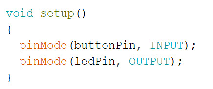
| void setup() | |
| { | |
| pinMode(buttonPin, INPUT); /* Initialize Button Pin as Output */ | |
| pinMode(ledPin, OUTPUT); /* Initialize LED Pin as Input */ | |
| } | |
| void loop() | |
| { | |
| buttonValue = digitalRead(buttonPin); /* Read the state of the Button into the variable: buttonValue */ | |
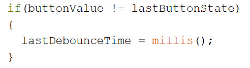
| /* Reset the debounce timer after button press */ | |
| if(buttonValue != lastButtonState) | |
| { | |
| lastDebounceTime = millis(); | |
| } | |
| /* Use the button state after waiting for debouncing */ | |
| if((millis() – lastDebounceTime) > debounceDelay) | |
| { | |
| if(buttonValue != buttonState) /* Check if the button state has changed */ | |
| { | |
| buttonState = buttonValue; | |
| if(buttonState == HIGH) /* If the button state is HIGH, toggle the LED state */ | |
| { | |
| ledState = !ledState; | |
| } | |
| } | |
| } | |
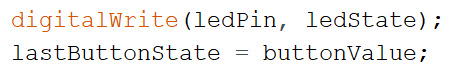
| digitalWrite(ledPin, ledState); /* Set the new state of the LED */ | |
| lastButtonState = buttonValue; /* Store the present button state for next loop */ | |
| } |
Working
This is a simple project where pressing a button would toggle the LED’s state, changing it from LOW to HIGH and vice versa. Let’s examine the code now to see how it functions.
The pin numbers for LED and Push Button are first defined. You can use “const int” variables instead of the “#define” macros that I used. For LEDs, GPIO5 or D1 is used, and for pushbuttons, GPIO4 or D2.
I then declared a few variables to store the LED and Push Button status (both current state and previous state of the button and the current state of the LED). There are a few other settings for using Button Debounce.
By utilising the pinMode() function and the necessary arguments in the setup() function, you initialise the “ledPin” as an output and the “buttonPin” as an input (OUTPUT and INPUT respectively).
In the first line of the loop() method, you read the button pin’s status using the digitalRead() function and save the result in the buttonValue variable.

The code’s button debounce section comes next. Utilize the button state value that was previously received after waiting until the debounce delay has passed since the button was pressed. Accidental pushes and noise will be removed as a result.
Only toggle the LED’s state if the button’s state has changed and if it is equal to HIGH.

Apply the new LED state using the digitalWrite() function, and store the button’s current state as well.
Sample Output Video
A brief segment of the output video is seen in the following gif.

Conclusion
I hope all of you had understand the basics of ESP8266 NodeMCU Input Output operations of the GPIO Pins. We MATHA ELECTRONICS will be back soon with more informative blogs.