
Interfacing I2C LCD with STM32F103C8T6 | STM32 I2C LCD Tutorial
This guide will demonstrate how to connect an I2C LCD to an STM32F103C8T6 MCU based STM32 Blue Pill Board. A simple connection between the LCD and STM32 allows for the display of data, as I demonstrated in the “Interfacing 16X2 LCD with STM32F103C8T6” tutorial. Using I2C Communication, I will be able to exchange data with a 162 LCD, making this an exciting project.

Introduction
Small alphanumeric character displays, such as the widely used 162 LCD Display, are a valuable addition to any project as they allow you to clearly show the status of the work in progress. The data shown on the LCD can be either general project information, such as a temperature reading from a sensor, or more specialized information, such as debug messages or error codes.
A 16×2 LCD display module has been integral to many of my projects, and I’ve used it with microcontrollers as diverse as the 8051, the ARM7-based LPC2148, the ATmega8, the Arduino UNO, and the PIC.

This is all well and good, but one drawback of a 162 LCD or even a bigger 204 LCD Display is that they require a huge number of pins in order to interface with a microcontroller. A minimum of six of the microcontroller’s pins are required to communicate with the LCD, even in 4-bit data mode (four for the Data Pins, one for the Register Select pin, and one for the Enable Pin, with the Write operation assumed, with R/W connected to GND).
If your project is simple, then using only six of the Microcontroller’s pins to connect to a character display might not seem like a big deal.
How to Interface I2C LCD with STM32F103C8T6?
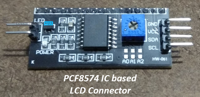
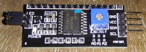
The PCF8574 GPIO Expander IC steps in to save the day. It comes with all the bells and whistles, such as a 10K POT for LCD contrast adjustment, pull-up resistors for I2C communication, I2C pins for connecting with a microcontroller, etc., as a dedicated module for interfacing a 162 LCD display.
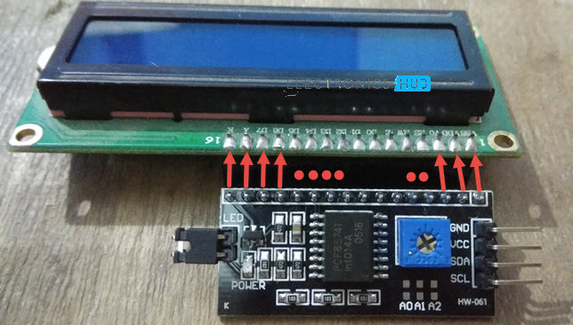
The I2C Pins of this module are easily connected to the appropriate I2C Pins of the STM32 Blue Pill Board by simply mounting it to the back of the 16×6 LCD display. That’s how easy it is.
PCF8574 Module
In this lesson on “Interfacing PCF8574 with Arduino,” I’ve already covered the PCF8574 GPIO Expander IC. I won’t go into everything here; instead, I’ll give a quick summary.
A 16-pin IC called the PCF8574 functions as an expander for I2C to 8-bit Parallel IO. What this means is that you can practically double the number of IO pins on your microcontroller by using I2C communication.
When purchasing a PCF8574 Module, it’s crucial to keep in mind that there are two types on the market. A generic IO Expander Module is one option; it can be utilised as, well, an IO expander.

The other module type is likewise based on the PCF8574 IC, but it is made to only work with LCD displays, such as 162 and even 204 LCDs. As a result, you must select the latter for this project because it has all the connections and components required to interface a 16X2 LCD Display.
Components Required
- STM32F103C8T6 MCU based STM32 Blue Pill Board
- PCF8574 IC based LCD Connector Module
- 16×2 LCD Display
- Connecting Wires
- USB to UART Converter Module (if programming through UART)
Circuit Diagram
The circuit diagram for the STM32 Blue Pill board’s I2C interface with the STM32F103C8T6 MCU is shown in the following image.

Connections Explained
This project’s relationships are pretty simple. Simply attach the PCF8574 Module to the 16-by-2 LCD’s back. Before connecting, verify the pins on the LCD and the PCF8574 Module. The PCF8574 Module’s I2C pins should be visible and accessible to the right of the display if everything is connected properly.
Connect the SDA pin of the PCF8574 Module to PB7 of the STM32 and the SCL pin to PB6 of the STM32 at this time. Connect the PCF8574 Module’s VCC and GND pins to 5V and GND, respectively. The connections are now complete.
Identifying the Slave Address of PCF8574 Module
To interface an I2C LCD display with an STM32, we must first get the PCF8574 Module’s slave address. Slave Address in I2C Communication must be known in advance because it is crucial.
By consulting the PCF8574 IC data sheet and the schematic for the PCF8574 I2C LCD Module, you may determine the slave address. Do not worry if you believe it to be a time-consuming process. The following code can also be used to determine the slave address. The Slave Address will be determined by this code and shown on the Serial Monitor.
Code
#include <Wire.h> void setup() { Wire.begin(); Serial.begin(9600); while (!Serial); } void loop() { byte error, address; int I2CDevices; Serial.println(“Scanning for I2C Devices…”); I2CDevices = 0; for (address = 1; address < 127; address++ ) { Wire.beginTransmission(address); error = Wire.endTransmission(); if (error == 0) { Serial.print(“I2C device found at address 0x”); if (address < 16) Serial.print(“0″); Serial.print(address, HEX); Serial.println(” !”); I2CDevices++; } else if (error == 4) { Serial.print(“Unknown error at address 0x”); if (address < 16) Serial.print(“0”); Serial.println(address, HEX); } } if (I2CDevices == 0) Serial.println(“No I2C devices found\n”); else Serial.println(“****\n”); delay(5000); } |
In my case, the slave address is 0X3F. So, I have to use this Slave Address in the actual Program for STM32.

Programming STM32 for I2C LCD Display
We can now create the software because the I2C LCD and STM32F103C8T6 MCU have been interfaced. For this module, a unique library called “LiquidCrystal I2C” was created. From this site, you may obtain this library. Extract the contents of the downloaded zip file and add them to your local Arduino installation’s libraries folder.
Initialize the LCD Module using the slave address we obtained from the previous code. Include the LCD’s row and character counts, which are 16 and 2, respectively.
You can get the characters you desire shown on the LCD by using the “print” feature of the library.
Code
#include <Wire.h> #include <LiquidCrystal_I2C.h> // Set the LCD address to 0x3F for a 16 chars and 2 line display LiquidCrystal_I2C lcd(0x3F, 16, 2); void setup() { lcd.begin(); lcd.backlight(); lcd.setCursor(0,0); lcd.print(” I2C LCD with “); lcd.setCursor(0,1); lcd.print(” STM32F103C8T6 “); } void loop() { // Do nothing here… } |
Conclusion
Hope this blog helps you to understand the Interfacing of I2C LCD with STM32F103C8T6. We, MATHA ELECTRONICS will come back with more informative blogs.