
I’ll demonstrate how to connect the HC-05 Bluetooth to the STM32F103C8T6 Blue Pill Board in this project. You may wirelessly interface with your STM32 MCU with another Bluetooth device, like a Smart Phone, by integrating a Bluetooth Module like the HC-05 or HC-06 with STM32.
I’ll use an Android phone with a Bluetooth app installed to demonstrate this project by using it to control an onboard LED attached to Pin PC13 of the MCU.
Introduction
One of the most widely utilized wireless communication protocols in embedded systems is Bluetooth. It is frequently utilized for data transfer and audio functions in consumer devices like mobile phones and laptops.
In reality, with the introduction of BLE (Bluetooth Low Energy), Bluetooth-based wireless headset development and use are at an all-time high (sorry, 3.5mm headphone jack zealots, myself included!).
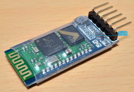
The HC-05 Bluetooth Module is the most widely used Bluetooth Module in the embedded world and has been for a very long time. It is a straightforward UART-based module with a 10 m range that operates at the standard 2.4 GHz wireless frequency.
Important Note
The same pins are utilised for communicating with the Bluetooth Module if you intend to programme your Blue Pill using UART (Pins PA9 and PA10).
Additionally, if you’re using USB programming, unplug the Bluetooth module from the STM32 Board, upload the program, and then plug it back in. Additionally, confirm that the BOOT Pin configurations are correct.
Circuit Diagram
The circuit diagram for interfacing the HC-05 Bluetooth module with the STM32F103C8T6 MCU is shown in the following figure.

Components Required
Hardware
- STM32F103C8T6 Blue Pill Board
- HC-05 Bluetooth Module
- Connecting Wires
- USB to Serial Adapter (if programming STM32 via UART)
- USB Cable
- Android-based Smart Phone
Software
- Any Bluetooth Terminal App for Android Phone
Please feel free to utilize any Bluetooth terminal App; I’m not giving any recommendations on the Bluetooth App. I used Kai Morich’s “Serial Bluetooth Terminal” to demonstrate the project. Use this URL if you wish to use the same.
Connections Explained
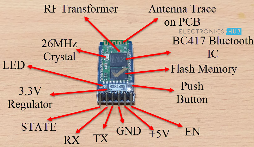
The STM32F103C8T6 Blue Pill Board and the HC-05 Bluetooth Module have fairly straightforward connections. The Bluetooth Module’s TX pin is connected to the MCU’s PA10 pin, while the RX pin is attached to the PA9 pin of the MCU.
The Blue Pill board’s 5V and GND pins can be used to link the VCC and GND of the HC-05 Bluetooth Module. For demonstration purposes, the onboard LED, which is attached to PC13, is used.
Interfacing HC-05 Bluetooth with STM32F103C8T6
Let’s move on to the actual HC-05 Bluetooth STM32F103C8T6 interface now that we have seen the circuit and connection. We must use the UART pins on the Blue Pill board to interface with the HC-05 Bluetooth Module because it relies on serial communication over UART.
To make things easier, I have interfaced with the HC-05 Bluetooth Module using the UART1 pins PA9 (TX) and PA10 (RX). When uploading the program, exercise caution.
You won’t run into any issues if you’re using a USB to UART converter to program the STM32 because those pins are also used for programming. Therefore, the Bluetooth Module must be unplugged in any case.
If you decided to transfer the application through the USB port, there is an issue. In this situation, you must cut off the Bluetooth Module’s PA9 and PA10 connections to the STM32.
The connection of the onboard LED is another crucial detail to keep in mind. The LED’s connection to the MCU’s PC13 pin is depicted in the accompanying image.

It is evident from this image that the LED will be turned ON when the PC13 pin is LOW and OFF when the PC13 pin is HIGH. As a result, I’ll use the same setup in the code to turn the LED on and off.
Code
Below is a list of the project’s code. It is quite easy to understand the code if you have already created an Arduino HC-05 Bluetooth Module interface because it is so simple.
| const int LEDPin = PC13; char inputData = 0; void setup() { Serial1.begin(9600); Serial1.println(“Electronics Hub”); Serial1.println(“HC-05 Bluetooth with STM32”); pinMode(LEDPin, OUTPUT); } void loop() { if(Serial1.available() > 0) { inputData = Serial1.read(); if(inputData == ‘0’) { digitalWrite(LEDPin, HIGH); Serial1.println(“LED is turned OFF”); } else if(inputData == ‘1’) { digitalWrite(LEDPin, LOW); Serial1.println(“LED is turned ON”); } } } |
In the example above, Serial1 denotes that I am communicating using UART1. You can also use the STM32F103C8T6’s UART2 or UART3 as long as the correct connections and initialization are made in the code.
Working
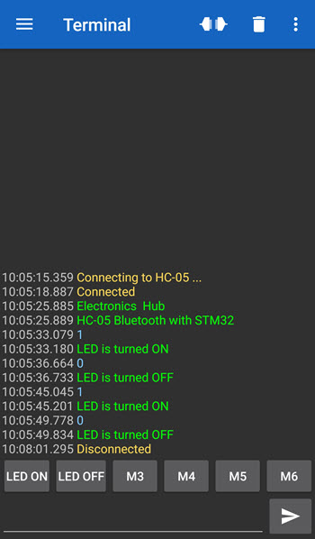
The project’s operation is fairly straightforward. Before connecting anything, upload the software to the STM32 Blue Pill and follow the circuit diagram’s directions. Then pair the HC-05 Bluetooth Module by going to the Bluetooth Settings on your Android smartphone.
It will inquire for a pin when pairing for the first time. In that scenario, type 0000 or 1234. It is 1234 in my situation. Open your Bluetooth terminal app on your Android phone and start looking for Bluetooth devices after pairing is complete. HC-05 Bluetooth Module should be chosen.
Set the app to send ‘1’ and ‘0’ at this point. The LED will be turned ON when the number “1” is transmitted and OFF when the number “0” is sent.
Conclusion
Hope this blog helps you to understand the Interfacing HC-05 Bluetooth with STM32F103C8T6 | STM32 Blue Pill. We, MATHA ELECTRONICS will come back with more informative blogs.