
In this project, I’ll demonstrate how to connect a servo motor to an STM32F103C8T6 Blue Pill Board and use a potentiometer and the MCU’s built-in PWM capability to operate it. You can apply your expertise of STM32 servo motor control to a variety of complex STM32-based projects.
Introduction
The workhorses of industrial automation are servo motors. They are frequently utilized in CNC machines, industrial robotics, and automation apparatus. The benefit of servo motors over other types of motors, such as stepper motors, is their ability to precise control either angular or linear position (depending on the application).
Small plastic gear type Servo Motors are particularly common among novices and enthusiasts when it comes to embedded systems. Small robots, robotic arms, solar panel positioning, and other related tasks all make use of them.
One of the most widely utilized servo motor types for small embedded applications is the TowerPro SG90. I myself have used it in a number of Arduino-based applications.
I’ll show how to interface a servo motor with the STM32F103C8T6 Blue Pill board in this project. I don’t have access to the frequently used TowerPro SG90 Servo Motor at the moment I’m putting my concept into action.
I have, however, been utilizing a somewhat larger TowerPro MG 996R Metal Gear Servo Motor in another robotic application. Even with the smaller SG 90 Servo Motors, you can follow through with this project as it is after I describe the servo motor’s specs.
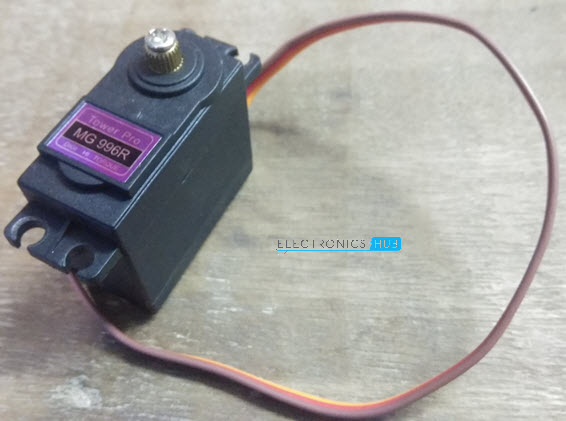
A Brief Note on MG 996R Servo Motor
A high torque servo motor with metal gears is the TowerPro MG 996R Digital Servo Motor. In contrast to the 1.8kg of the SG90, it can deliver an average stalling torque of 10kg.
The MG996R rotates at an angle of around 120 degrees, or 60 degrees in each direction. When compared to the SG90 Servo’s 180 degrees of rotation, this is less.
The MG996R Servo Motor’s specifications are listed below.
- Weight – 55g
- Stall Torque – 9.4 kgf-cm at 4.8V and 11 kgf-cm at 6V
- Voltage – 4.8V – 7.2V
- Running Current – 500mA – 900mA at 6V
- Stall Current – 2.5A at 6V
The MG996R contains three pins, including an orange PWM pin, a red VCC pin, and a brown ground pin, just as the SG90. The locations 0, 60, and -60 can be set at pulse 1.5ms, 2ms, or 1ms depending on the PWM signal’s 20ms period.
Interfacing Servo Motor with STM32F103C8T6
Even though the MG 996R Servo Motor is bigger and more powerful, the connections with respect to the MCU are similar to that of an SG90 Servo Motor. The Orange Wire must be connected to any PWM pin of the MCU.
For controlling the position, a potentiometer can be used and as per the readings from the ADC (whose input is the POT), the angle of rotation can be adjusted.
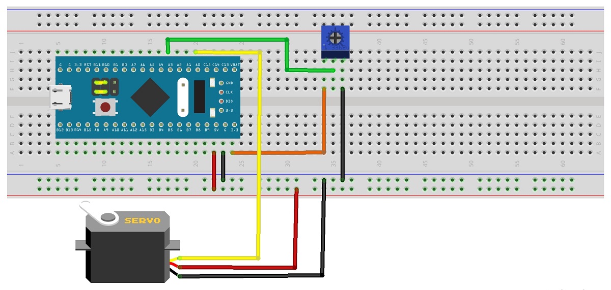
Circuit Diagram
The circuit diagram for connecting a servo motor to the STM32F103C8T6 Blue Pill board is shown in the accompanying figure.
Components Required
- STM32F103C8T6 Blue Pill Board
- Servo Motor
- 10KΩ Potentiometer
- Connecting Wires
- USB to UART Adapter (if programming via UART)
Connections Explained
The STM32F103C8T6 MCU’s ADC and PWM pins must be used for this project. The pin layout of the STM32F103C8T6 MCU is displayed in the following image.

As you can see, there are 15 PWM pins and 10 ADC pins (PA0 to PA7 and PB0 to PB1) (PA0 – PA3, PA6 – PA10, PB0 – PB1, PB6 – PB9).
As a result, PA3 is used as an ADC pin to connect the POT, and PA0 is utilized as a PWM pin to connect the PWM pin of the servo motor.
Programming STM32 for Servo Motor Control
If you have any experience integrating a servo motor with an Arduino board, developing the code for controlling a servo motor with the STM32F103C8T6 Blue Pill is actually rather straightforward. You must keep in mind one thing, though, regarding the ADC.
You will see that the ADC has a 12-bit resolution if you look at the STM32F103C8T6 MCU’s data page. This means that the STM32F103C8T6 ADC’s output will range from 0 to 212, or 0 to 4096.
Regarding the MG 996R Servo Motor’s specifications, the maximum rotation angle is 120 degrees. Therefore, in the program, we must divide the output value of the ADC by 4096/120, or 34, in ord
er to transfer the range 0–4096 to the angle 0–120.
If your servo motor is an SG90, and its maximum angle is 180 degrees, you must divide the ADC output by 22.
Code
The simple code for connecting a servo motor to the STM32F103C8T6 MCU is shown below.
#include<Servo.h> int servoPin = PA0; int potPin = PA3; int potValue = 0; int servoAngle = 0; Servo myServo; void setup() { myServo.attach(servoPin); } void loop() { potValue = analogRead(potPin); servoAngle = (potValue/34); myServo.write(servoAngle); delay(100); } |
Working
The project’s operation is fairly straightforward. The STM32 Blue Pill MCU’s ADC first reads the potentiometer’s value. The output of the ADC is then scaled to the servo motor’s angle of rotation.
The servo motor is turned to that specific angle using this value. As an alternative, you may create complete sweep capabilities between 0 and 120 degrees (in the case of MG 996R Servo).
Conclusion
Hope this blog helps you to understand Controlling a Servo Motor with STM32F103C8T6 Blue Pill. We, MATHA ELECTRONICS will come back with more informative blogs.