
In this tutorial, we will learn about the ADC Peripheral in ESP32. The Analog to Digital Converter or simply ADC od ESP32 is very useful to measure analog voltages from different sensors (like LM 35 Temperature Sensor), and potentiometers (for adjusting the brightness of LED), etc. Learn how to use ESP32 ADC Peripheral by understanding its characteristics, pins, functions, and also a couple of demonstration circuits.

A Brief Note on ESP32 ADC Peripheral
Two Analog to Digital Converters of the Successive Approximation Register (SAR) kind makes up the ESP32 SoC. (ADC). The two SAR ADCs, ADC1, and ADC2, in the ESP32, have a total of 18 channels. 8 channels make up ADC1 and 10 channels make up ADC2.

Yes, the resolution of the ADC in the ESP32 is customizable and has various settings including 9-bit, 10-bit, 11-bit, and 12-bit. The maximum resolution of the ADC in the ESP32 is 12-bits. If not altered, the resolution is typically set to 12-bit.
Because the ESP32 ADC’s default resolution is 12-bit, the output digital values can contain 212 = 4096 values, which means that by default, the output will be a value between 0 and 4095. The ESP32 ADC can measure analog voltage in the range of 0V to 3.3V because the ADC input voltage limit is 3.3V.
ADC Pins of ESP32
The ADC pins are fixed, meaning that you must utilize the preset GPIO Pins that contain ADC capabilities and cannot be software configured, unlike some digital peripherals (PWM, software SPI, and I2C). You must be aware of some restrictions, though.
ESP32 features 18 channels of ADC, however, not all of them are accessible to users. Only 6 of the 8 ADC1 channels (ACD1 CH0, ACD1 CH3 to ACD1 CH7) are available; ADC1 CH1 and ADC1 CH2 are not (even the pins are not exposed in the ESP32 Development Board).

Even with ADC2 (assuming Wi-Fi is not being used), not all of the pins are immediately available because some of them are needed for other crucial purposes (Boot Strapping).
The ADC Channels, GPIO Pins, Arduino style names (A0, A1, etc.), and other key information are listed in the table below.
The following table shows the ADC Channels, Arduino style names (A0, A1, etc.), GPIO Pins and any important points to remember.
| ADC Channel | Pin Name | GPIO Pin | Notes |
| ACD1_CH0 | A0 | GPIO 36 | Free to use / Hall Sensor Pin |
| ACD1_CH1 | GPIO 37 | Not available | |
| ACD1_CH2 | GPIO 38 | Not available | |
| ACD1_CH3 | A3 | GPIO 39 | Free to use / Hall Sensor Pin |
| ACD1_CH4 | A4 | GPIO 32 | Free to use |
| ACD1_CH5 | A5 | GPIO 33 | Free to use |
| ACD1_CH6 | A6 | GPIO 34 | Free to use |
| ACD1_CH7 | A7 | GPIO 35 | Free to use |
| ACD2_CH0 | A10 | GPIO 4 | |
| ACD2_CH1 | A11 | GPIO 0 | Used as BOOT Pin / Not available |
| ACD2_CH2 | A12 | GPIO 2 | Used as BOOT Strapping Pin |
| ACD2_CH3 | A13 | GPIO 15 | Used as BOOT Strapping Pin |
| ACD2_CH4 | A14 | GPIO 13 | |
| ACD2_CH5 | A15 | GPIO 12 | |
| ACD2_CH6 | A16 | GPIO 14 | |
| ACD2_CH7 | A17 | GPIO 27 | |
| ACD2_CH8 | A18 | GPIO 25 | |
| ACD2_CH9 | A19 | GPIO 26 |
It is safe to assume that the 6 available ADC1 pins (ACD1 CH0 and ACD1 CH3 to ACD1 CH7) can be used without any ambiguity after taking into account all of the information provided above.
Additionally connected to the Hall Effect Sensor are ADC1 CH0 and ADC1 CH3.
There can be limitations specific to other ESP32 Development Boards. Therefore, make sure to consult the datasheet and schematic to determine whether a specific ADC pin is available for usage or not.
ADC Functions
The ADC driver has nine functions available. As follows:
- analogRead(pin): Get the ADC Value for the specified pin.
- Get the ADC Value for the specified pin with analogRead(pin).
- Set the output resolution of analogRead with the analogReadResolution(bits) function. Bits can range from 9 to 12, with the default value being 12.
- Sets the sample bits and read resolution with analogSetWidth(bits). The range is 9 to 12, with a 12-bit default.
- Set the ADC clock’s divider using the function analogSetClockDiv(clockDiv).
- Set the attenuation for all channels with analogSetAttenuation(attenuation). The default value is 11db, but other options include 0db, 2 5db, 6db, and 11db.
- Set the attenuation for a specific pin using the analogSetPinAttenuation(pin, attenuation) function.
- Attach pin to ADC with adcAttachPin(pin) (done automatically in analogRead).
- If the ESP32 is not already calibrated, use analogSetVRefPin(pin) to set the pin to use for the ADC calibration. Pins 25, 26, or 27 may be used.
- Get the millivolt value for pin using analogReadMilliVolts(pin).
Measure Analog Voltage
Now that the theory, pin details, and library operations have been outlined, we can begin to create circuits that actually use the ESP32 ADC Peripheral. Let’s look at how to set up the ESP32’s ADC channel for the first project and measure an analogue voltage applied to one of the ADC Pins. [Projects for Novice ESP32 Users]
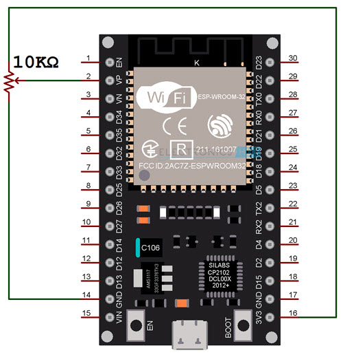
Using a potentiometer is the easiest approach to provide changeable analogue voltage. Connect the ends of the POT to the ESP32 Development Board’s 3.3V and GND, and the Wiper to any available ADC Pin. To make things straightforward, I selected GPIO 36 (A0), also known as ADC1 CH0, as the ADC Pin.
Components Required
- ESP32 DevKit Development Board
- 10 KΩ Potentiometer
- Breadboard
- Connecting Wires
- 5mm LED
- 220Ω Resistor
Circuit Diagram
The circuit diagram for using the ESP32’s ADC to measure analogue voltage is displayed in the accompanying image.
Code
If you’ve ever worked with the Arduino or ESP8266 ADC, the code is extremely simple to understand. Using the “analogRead” function, read the ADC value from the ADC Pin (in this case, A0), convert the digital value to voltage using a quick computation, and display the result on Serial Monitor.
| #define ADCPIN A0 | |
| int adcValue; | |
| float voltValue; | |
| void setup() | |
| { | |
| Serial.begin(115200); | |
| } | |
| void loop() | |
| { | |
| adcValue = analogRead(ADCPIN); | |
| voltValue = ((adcValue * 3.3) / 4095); | |
| Serial.print(“ADC Value = “); | |
| Serial.print(adcValue); | |
| //delay(1000); | |
| Serial.print(” “); | |
| Serial.print(“Voltage = “); | |
| Serial.print(voltValue); | |
| Serial.println(” V”); | |
| delay(1000); | |
| } | |
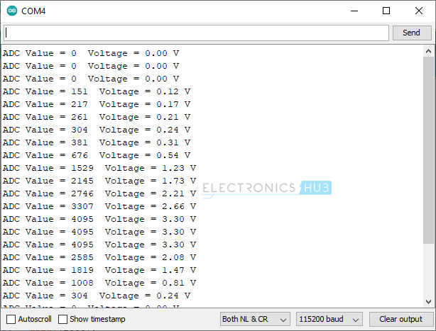
The output of the Serial Monitor looks something like this:
LED PWM using ESP32 ADC
The PWM Pin is GPIO 16, and the ADC Pin is still A0 (ADC1 CH0 – GPIO 36), just as before. With the aid of a 220 current-limiting resistor, I connected a 5mm Red LED to this pin.
Circuit Diagram
The circuit diagram for manually regulating the duty cycle of PWM using ESP32’s ADC and subsequently altering an LED’s brightness is shown in the accompanying image.

Code
| #define ADCPIN A0 |
| const int LEDPin = 16; /* GPIO16 */ |
| uint16_t dutyCycle; |
| const int PWMFreq = 5000; |
| const int PWMChannel = 0; |
| const int PWMResolution = 12; |
| const int MAX_DUTY_CYCLE = (int)(pow(2, PWMResolution) – 1); |
| //const int ADC_RESOLUTION = 4095; |
| void setup() |
| { |
| /* Initialize PWM Channels with Frequency and Resolution */ |
| ledcSetup(PWMChannel, PWMFreq, PWMResolution); |
| /* Attach the LED PWM Channel to the GPIO Pin */ |
| ledcAttachPin(LEDPin, PWMChannel); |
| } |
| void loop() |
| { |
| /* Read Analog Input from three ADC Inputs */ |
| dutyCycle = analogRead(ADCPIN); |
| /* Map ADC Output to maximum possible dutycycle */ |
| //redDutyCycle = map(redDutyCycle, 0, ADC_RESOLUTION, 0, RED_MAX_DUTY_CYCLE); |
| /* Set PWM Output of Channel with desired dutycycle */ |
| ledcWrite(PWMChannel, dutyCycle); |
| delay(10); |
| } |
Conclusion
Hope this blog helps you to understand How to use ADC in ESP32. We, MATHA ELECTRONICS will come back with more informative blogs.
Excelent blog. Many thanks.