
Communication protocols have a specific role in embedded systems because they make it possible for components to communicate data effectively. In the embedded world, there are many different protocols, but we will encounter a few more frequently than others. We polled online groups of embedded engineers and enthusiasts and came up with a list of seven communication protocols that are quite popular and worth knowing about.

1. SPI(Serial Peripheral Interface) Protocol:
The SPI is a full-duplex protocol that establishes communication using a master-slave arrangement. This protocol was created by Motorola in 1980. Microcontrollers with interfaces such as EEPROM, LCD screens, etc. use SPI.

The SPI protocol uses four pins:
- SCLK: Serial Clock ( Clock source for data transmission )
- MOSI: Master Output Slave Input (Output data from Master)
- MISO: Master Input Slave Output (Output data from Slave)
- SS: Slave Select ( Slave selection from multiple slaves by Master)
When a master device has to control more than one slave, more SS pins are required. Multiple slaves can be commanded by one master. SPI protocol provides high-speed data transport, and as buses are commonly run at 50 MHz, data transmission rates can reach 50 Mbps.
- Data Transmission:
Using the Slave Select pin and a low input signal, the master device must choose the slave to which the data must be transferred. The transmission will then be synchronized by sending the clock pulse from the SCLK pin to the slave. Data from the master pin is sent through the MOSI pin, while information from the slave is sent through the MISO pin.
2. I2C(Inter-Integrated Circuit) Protocol:
The I2C protocol for two-wire serial bus communication was developed by Philips Semiconductors in 1982. It is a two-wire communication interface that is frequently used in embedded systems to link peripherals like microcontrollers, A/D and D/A converters, and I/O devices.

I2C establishes a connection using two pins:
- SDA: Serial Data Line
- SCL: Serial Clock Line
Depending on how it operates, the I2C protocol supports various data speeds. Data transfer rates of 100 kbit/s in normal mode and 400 kbit/s in full speed mode are both possible.
- Data Transmission:
Each device in the I2C protocol is assigned a unique address. When a master wants to send data to a slave, it uses the SDA pin to send the address of the slave device that the message is meant for. Only the slave with the provided address will take this incoming data, which is followed by a Data frame.
3. USART(Universal Synchronous/Asynchronous Receiver/Transmitter) Protocol:
The serial communication protocol known as USART was created by Digital Equipment Corporation in the 1960s. Full duplex, half-duplex, and simplex communication are all supported. Nearly all microcontrollers will support this protocol, which is one of the most popular ones.

In UART, two pins are used for communication.
- RX: Receive the incoming data
- TX: Transmits the outgoing data
In USART, data is transmitted using data packets, which typically have 8 data bits, 2 start bits, and 1 parity bit for error correction.
- Data Transmission:
As previously indicated, data in USART will be transmitted as data frames or data packets. A start bit precedes the data bits in a data frame, which are then followed by the parity and stop bits. The majority of microcontrollers offer options for configuring the data frame’s structure and bit count.
4. CAN(Control Area Network) Protocol:
To simplify communication and wiring, the Controller Area Network (CAN) protocol was created to transfer data among various interfaces. This was initially created and utilized in automobiles to establish communication between various components, including as the engine, brakes, air conditioner, etc. while minimizing wiring in the vehicle. The distinctive quality of the CAN protocol is that every device connected to the CAN bus will have access to any data transmitted by anyone CAN devise or node.
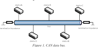
In order to communicate with other CAN devices, this protocol utilizes two wires.
- CAN HIGH
- CAN LOW
There are two types of CAN protocols: Standard CAN and Extended CAN.
- Data Transmission:
Any node in standard CAN can send data to any other node via the bus. CAN data frames begin with a start bit, which is followed by an identifier that is 11 bits long and establishes the message’s priority. When two devices try to send messages simultaneously over the CAN bus, the message with the higher priority is allowed access. The RTR bit determines whether or not a specific node is being sought for the data. The IDE bit identifies if the CAN frame is regular or extended. Bits that indicate the length of the data are followed by the data length code (IDE). The message itself follows. Following that, cyclic redundancy check and ACK bits are employed to error-check data transfer to assure appropriate operation. an end-of-frame 7 bit which marks the end of the message.
5. USB(Universal Serial Bus) Protocol:
One of the most popular and well-developed communication protocols is USB. Although it has several standards and hardware varieties, it is regarded as flexible and efficient in embedded systems. Polling is the method used in a USB connection, where the host device starts the data transfer. A device allocates an address to the host when it connects to it, and it utilizes that address to transport data.

USB protocol uses the below pins to function
- VCC – For power supply
- GND – To close the circuit
- D+ – Data transfer differential line
- D- – Data receive differential line
- Data Transmission:
Data packets are used for every data transfer in a USB communication. A data packet typically consists of three parts: a token packet that contains information about the data type and device address. The actual data to be sent is then contained in a data packet, which is followed by an EOP signaling the end of the data packet.
6. ETHERNET Protocol
The most used networking protocol, Ethernet, is used to create connections from LAN to WAN. This protocol has become crucial in embedded systems with the growth of IoT. Over the years, this communication protocol has undergone a number of changes to improve its connectivity and speed. To enable Ethernet connectivity, ordinary microcontrollers are typically paired with Ethernet controller chips like the WZ1500. However, some expensive microcontrollers, such as the STM32, will include some built-in support for the Ethernet protocol. These microcontrollers transmit and receive data across networks using the MII or RMII protocol.

- Data Transmission:
Data frames are used in the Ethernet protocol for data transmission. This data frame is made up of bits for error correction, the sender’s address, the receiver’s address, and the actual data.
7. RS-485 Protocol:
Another widely used protocol for tying microcontrollers to external peripherals is RS-485. When data must be communicated over distances of more than a few hundred meters, this protocol is particularly helpful. Most microcontrollers utilize external chips like MAX485 to use this communication, similar to the Ethernet protocol. Several devices can communicate data using the same interface when using this protocol. These pins are used in the RS-485 protocol.
- TX+
- TX-
- RX+
- RX-
- Data Transmission:
Start bits, receiver address, data bits, and stop bits to signal the end of transmission make up an average RS-485 data frame.
Conclusion
I hope all of you understand the basics of the seven communication protocols. We MATHA ELECTRONICS will be back soon with more informative blogs.