
Hello, we’ve previously gone over the STM32 discovery board introduction. Today we will connect the Infrared Sensor to the STM Board. If you are new to STM programming, you will grasp interrupt handling and the usage of GPIO pins. Let’s get this party started!

STM32 DISCOVERY BOARD
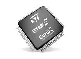
STM32 Discovery Board is designed as a development board that is similar to Arduino in terms of advanced capabilities and accessibility. The STM32F407 Discovery Board enables the development of high-reliability applications by utilizing an advanced performance microcontroller known as the Arm Cortex-M4 32-bit core. I’m assuming you’re familiar with ARM Architecture. It provides versatility and customization, allowing you to experiment with libraries, communication protocols, GPIO pins, and so on.
IR SENSOR
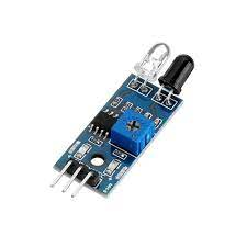
The infrared Obstruction Sensor Module has an IR transmitter and receiver that emits IR energy and detects reflected IR energy to detect the existence of any obstacle in front of the sensor module. A potentiometer is located on the PCB of this electrical circuit. The integrated potentiometer allows users to fine-tune the detecting range. Even in low light or full darkness, the sensor provides a very good and reliable response.
SPECIFICATIONS:
- Operating Voltage: 3.0V – 5.0V
- Detection range: 2cm – 30cm (Adjustable using potentiometer)
- Current Consumption:at 3.3V : ~23 mA,at 5.0V: ~43 mA
- Active output level: Outputs Low logic level when an obstacle is detected
- Onboard Obstacle Detection LED indicator

An IR sensor is made up of an IR LED and an IR Photodiode, which are referred to together as a Photo–Coupler or Opto–Coupler. As previously stated, the Infrared Obstacle Sensor has an IR transmitter and receiver. A light-emitting diode (LED) that produces infrared radiation is known as an infrared transmitter. As a result, they are known as IR LEDs. Even though an IR LED seems to be a regular LED, the radiation it emits is invisible to the naked eye.
Components Required for Interfacing:
- STM32F407 Discovery Board
- Infrared Sensor
- LEDs
- Breadboard
- Jumpers
- USB type A to Mini B Cable.
Interfacing Diagram:

The interface between the IR module and the STM32 DISC Board is shown in the image above. When the IR sensor finds an obstruction, the PA1 pin generates an interrupt. The LED linked to PD1 displays the state of the interrupt.
Pinout:
- LED1- PD0 (Pin 0 of Port D)
- LED2- PD1 (Pin 1 of Port D)
- IR (5V)- 5V of STM Board
- IR (Gnd)- GND of STM
- IR (Dout)- PA1 (Pin 1 of Port A)
IR Sensor Interfacing with STM32
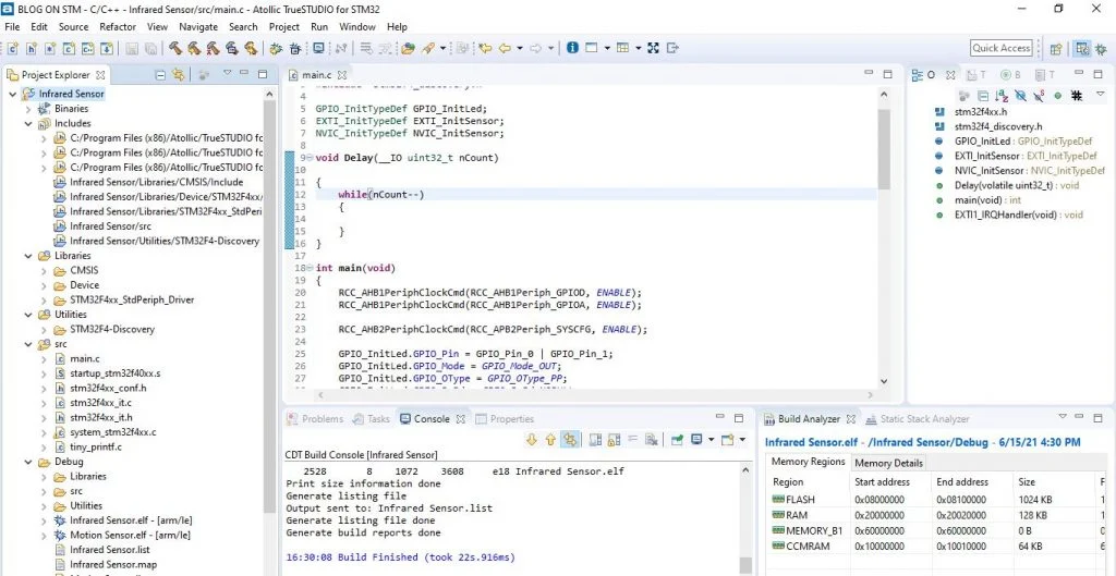
Let’s get started on developing code and deploying it. I programmed the board using Atollic Truestudio. The first steps are to install software and pick a board. After that, navigate to Files—>New Project—>C project, and the new project’s viewpoint will appear, as seen in the figure below.
- Step 1: Create New Project.
- Step 2: Write Code.
- Step 3: Save.
- Step 4: Build Project.
- Step 5: Debug.
- To run the code on the STM32 Board, click the resume button in the Debugger perceptive.

Coding Explanation
- STM32F GPIO pins are labelled as Port A, Port B, Port C, and so on. By default, all of these ports are dormant. If we must utilise them, we must enable the clock at a specific GPIO.
| RCC_AHB1PeriphClockCmd(RCC_AHB1Periph_GPIOD, ENABLE); //Enable GPIOD clock RCC_AHB1PeriphClockCmd(RCC_AHB1Periph_GPIOA, ENABLE); //Enable GPIOA clock RCC_AHB2PeriphClockCmd(RCC_APB2Periph_SYSCFG, ENABLE); // Enable SYSCFG clock |
| GPIO_InitLed.GPIO_Pin = GPIO_Pin_0 | GPIO_Pin_1; // GPIOs as output push-pull to drive external GPIO_InitLed.GPIO_Mode = GPIO_Mode_OUT; // Define as output port. GPIO_InitLed.GPIO_Speed = GPIO_Speed_50MHz |
- These pins’ speeds cannot be exactly 50MHz. However, by utilizing this line, we are attempting to get the highest potential speed.
| GPIO_Init(GPIOD, &GPIO_InitLed);// Apply all above configurations. |
- STM32 boards typically include a total of 23 interrupt sources, which are divided into two categories. On each port, one portion is for GPIO pins from P0 to P15, while the other is for RTC, Ethernet, and USB interrupts. We can’t utilise PA0 and PB0 at the same time because they’re both linked to Line 0. However, because they are linked to distinct lines, PA2 and PA6 can be utilized concurrently.
| SYSCFG_EXTILineConfig(EXTI_PortSourceGPIOA, EXTI_PinSource1);//Connect EXTI at Line1 to PA1 pin |
| /*Configuration of EXTI at Line1.*/ EXTI_InitSensor.EXTI_Line = EXTI_Line1;EXTI_InitSensor.EXTI_Mode = EXTI_Mode_Interrupt;EXTI_InitSensor.EXTI_Trigger = EXTI_Trigger_Rising;EXTI_InitSensor.EXTI_LineCmd = ENABLE;EXTI_Init(&EXTI_InitSensor); |
| NVIC_InitSensor.NVIC_IRQChannel = EXTI1_IRQn;// Selection of interrupt |
- The lines below define the priority level of the interrupt. In other words, the highest priority interrupt has a lower value ranging from 0x00 to 0x0F.
| NVIC_InitSensor.NVIC_IRQChannelPreemptionPriority = 0; NVIC_InitSensor.NVIC_IRQChannelSubPriority = 0; NVIC_InitSensor.NVIC_IRQChannelCmd = ENABLE;// enable interrupt. |
| void EXTI1_IRQHandler(void) // interrupt Handler for pin1 connected to line 1 { if(EXTI_GetITStatus(EXTI_Line1) != RESET) { GPIO_WriteBit(GPIOD, GPIO_Pin_1, Bit_SET); Delay(33600000); GPIO_WriteBit(GPIOD, GPIO_Pin_1, Bit_RESET); } } // Interrupt handler |
| EXTI_ClearITPendingBit(EXTI_Line1);// Clear the EXTI line pending bit. |
- Complete Program
#include "stm32f4xx.h"
#include "stm32f4_discovery.h"

GPIO_InitTypeDef GPIO_InitLed;
EXTI_InitTypeDef EXTI_InitSensor;
NVIC_InitTypeDef NVIC_InitSensor;

void Delay(__IO uint32_t nCount)

{
	while(nCount--)
	{

	}
}

int main(void)
{
	RCC_AHB1PeriphClockCmd(RCC_AHB1Periph_GPIOD, ENABLE);
	RCC_AHB1PeriphClockCmd(RCC_AHB1Periph_GPIOA, ENABLE);

    RCC_AHB2PeriphClockCmd(RCC_APB2Periph_SYSCFG, ENABLE);

	GPIO_InitLed.GPIO_Pin = GPIO_Pin_0 | GPIO_Pin_1;
	GPIO_InitLed.GPIO_Mode = GPIO_Mode_OUT;
	GPIO_InitLed.GPIO_OType = GPIO_OType_PP;
	GPIO_InitLed.GPIO_PuPd = GPIO_PuPd_NOPULL;
	GPIO_InitLed.GPIO_Speed = GPIO_Speed_50MHz;
        GPIO_Init(GPIOD, &GPIO_InitLed);

	GPIO_InitLed.GPIO_Pin = GPIO_Pin_1;
	GPIO_InitLed.GPIO_Mode = GPIO_Mode_IN;
	GPIO_InitLed.GPIO_Mode = GPIO_OType_PP;
	GPIO_InitLed.GPIO_PuPd = GPIO_PuPd_DOWN;
	GPIO_InitLed.GPIO_Speed = GPIO_Speed_50MHz;
	GPIO_Init(GPIOA, &GPIO_InitLed);


	SYSCFG_EXTILineConfig(EXTI_PortSourceGPIOA, EXTI_PinSource1);

	EXTI_InitSensor.EXTI_Line = EXTI_Line1;
	EXTI_InitSensor.EXTI_Mode = EXTI_Mode_Interrupt;
	EXTI_InitSensor.EXTI_Trigger = EXTI_Trigger_Rising;
	EXTI_InitSensor.EXTI_LineCmd = ENABLE;
	EXTI_Init(&EXTI_InitSensor);

	NVIC_PriorityGroupConfig(NVIC_PriorityGroup_1);

	NVIC_InitSensor.NVIC_IRQChannel = EXTI1_IRQn;
	NVIC_InitSensor.NVIC_IRQChannelPreemptionPriority = 0;
	NVIC_InitSensor.NVIC_IRQChannelSubPriority = 0;
	NVIC_InitSensor.NVIC_IRQChannelCmd = ENABLE;
	NVIC_Init(&NVIC_InitSensor);

	while (1)
  {
	GPIO_WriteBit(GPIOD, GPIO_Pin_0, Bit_SET);
	Delay(16800000);
	GPIO_WriteBit(GPIOD, GPIO_Pin_0, Bit_RESET);
	Delay(16800000);
  }
}
void EXTI1_IRQHandler(void)
{
	if(EXTI_GetITStatus(EXTI_Line1) != RESET)
	{
		GPIO_WriteBit(GPIOD, GPIO_Pin_1, Bit_SET);
		Delay(33600000);
		GPIO_WriteBit(GPIOD, GPIO_Pin_1, Bit_RESET);
		EXTI_ClearITPendingBit(EXTI_Line1);
     }

}
OUTPUT:
In the output, we can see that IR LED keeps Blinking when an Obstacle is detected.