
Want to freshen up your ESP8266 IoT applications with some graphics? Or would you like to see your ESP8266’s IP address without using serial output. These super-cool OLED (Organic Light-Emitting Diode) screens could be just what you’re looking for! They’re incredibly light, virtually paper-thin, potentially flexible, and provide a brighter, more sharp image.
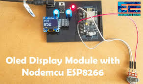
In this blog, we’ll learn how to use the Arduino IDE to connect an SSD1306 OLED to an ESP8266 NodeMCU. We’ll go over how to use the ESP8266 to show simple text, set pixels, and draw lines and shapes on an OLED display. We will also use the OLED panel to display monochrome bitmap pictures. So here we are. “Hello World” is the first sentence we print on our Display window, Serial monitor, or any other LCD. So, with this tutorial, we’ll print “Hello world,” and then move on to custom fonts and custom images on an OLED display.
What is an OLED?
Organic Light Emitting Diode, or Organic LED, is the abbreviation for Organic Light Emitting Diode. It’s a display technology made up of OLED panels that, when an electric current is sent through them, emit their own light. As a result, OLEDs are extremely light, have a true contrast ratio (that is, their whites are brighter and their blacks are darker than conventional electronic displays), have a wide colour gamut, deep colour saturation, and a wide viewing angle.

Displaying information is one of the crucial steps in electronic projects. So using OLED has always been one of the most popular ways to display information. This 0.96 inch 4 pin OLED module can be interfaced with any microcontrollers using SPI/IIC protocol. These modules offer high brightness, high contrast ratio, low power consumption, slim thin outline, and wide viewing angle. Blue OLED module consists of a display board, a display, a 4pin male header that pre-soldered on the breadboard. This is compact in size and provides a high resolution of 128*64. Here OLED has a self-light technology as a result it does not require a backlight. Thus it possesses high application for all types of display and considered as the ultimate technology for the next generation. This module ensures low power consumption in which 0.04 W required during normal operations.
SPECIFICATIONS:
- OLED Driver IC: SSD1306
- Resolution: 128 x 64
- Visual Angle: >160°
- Display Color: Area Color (White)
- Input Voltage: 3.3V ~ 6V
- Compatible I/O Level: 3.3V, 5V
- Only Need 2 I/O Port to Control
- Full Compatible with Arduino
- Working temperature: -30°C ~ 70°C
- Interface: I2C
- Super High Brightness (Adjustable)
- Super High Contrast (Adjustable)
- Embedded Driver/Controller
OLED PINOUT:

| 1 | VCC | Power supply input: 2.8 – 5.2V |
| 2 | GND | Ground |
| 3 | SCL | The serial clock input. |
| 4 | SDA | The serial data input/output. |
Parts of an OLED
A typical OLED is made up of six layers, with the seal (top layer) and the substrate being the two outermost layers (the bottom layer). The cathode (a negative terminal) and anode (a positive terminal) follow (a negative terminal). The emissive and conductive layers are sandwiched between these layers.

OLED WORKING
OLED (Organic Light-Emitting Diode) defined as a self-light-emitting technology composed of a thin, multi-layered organic film placed between an anode and cathode. Here the organic material itself has a property known as Electroluminescence (EL). This results in the material “glow” when stimulated by a current or an electric field. It is the best energy-saving display board featuring much less thickness than LCD displays with better brightness and also produces better and true colors. This compact-sized display module adds a great user interface experience to our electronics project. This 0.96″ OLED Display Module provides blue text on black background with very good contrast when a voltage of DC 2.8V is supplied. It also offers a very wide viewing angle of about greater than 160°.

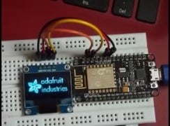
Schematic ESP8266 with OLED
VCC, GND, SCK, and SDA are the four pins of the OLED I2C module. There are a number of SMD resistor and capacitor components on the backside of the OLED module. The OLED display’s wiring is straightforward. SCK pin to D1 pin of NodeMCU, SDA pin to D2 pin of NodeMCU, and VCC and GND to VCC and GND of NodeMCU. I2C (Inter-Integrated Circuit, or IIC) is the data connection, and this interface is also known as TWI (Two Wire Interface).Follow the schematic diagram below for the ESP8266 module and connect them accordingly.

NOTE:
- Always double-check before connecting it to your project because the on-board pins may be in a different order.
- The operating voltage ranges from 3 to 5 volts, however the manufacturer’s datasheet is the best source of information.
Installing Library for OLED Display Module
To control the OLED display with the ESP8266, there are numerous libraries available. We’ll use two Adafruit libraries in this tutorial: the Adafruit SSD1306 library and the Adafruit GFX library.
There are two methods by which you can install this two libraries,
Method 1
- Open your Arduino IDE and Go to the path : Sketch/ Include libraries/manage libraries
- Go to the “Library Manager” and search “adafruit_SSD1306” and “adafruit_gfx”
Then type this two libraries into searchbox , select latest version and hit install.

Method 2:
You may also download these two libraries.
Afterwards,Copy the Adafruit SSD1306-master folder from the downloaded zipped file into the Arduino libraries folder once it has been downloaded. On Windows PCs, this folder is commonly located in Documents > Arduino > libraries. It’s normally located in the home folder > Arduino > libraries on Linux.
Code
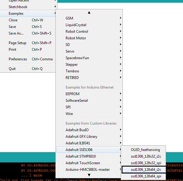
Now Go to File/example /Adafruit_SSD1306/ssd1306_128x64_i2c
#define SCREEN_HEIGHT 64 // OLED display height, in pixels
If you are gonna use here, for 128×32 display you have to write there 32 instead of 64 , As we are using 128×64 OLED display, we will keep it as a 64
and in line,
#define OLED_RESET 4 // Reset pin # (or -1 if sharing Arduino reset pin)
Write LED_BUILEDIN instead of 4 for programming OLED with NodeMCU like this:
#define OLED_RESET LED_BUILETIN // Reset pin
The program will look like this,
| #include <SPI.h> #include <Wire.h> #include <Adafruit_GFX.h> #include <Adafruit_SSD1306.h> #define SCREEN_WIDTH 128 // OLED display width, in pixels #define SCREEN_HEIGHT 64 // OLED display height, in pixels // Declaration for an SSD1306 display connected to I2C (SDA, SCL pins) #define OLED_RESET LED_BUILTIN // Reset pin # (or -1 if sharing Arduino reset pin) Adafruit_SSD1306 display(SCREEN_WIDTH, SCREEN_HEIGHT, &Wire, OLED_RESET); #define NUMFLAKES 10 // Number of snowflakes in the animation example #define LOGO_HEIGHT 16 #define LOGO_WIDTH 16 static const unsigned char PROGMEM logo_bmp[] = { B00000000, B11000000, B00000001, B11000000, B00000001, B11000000, B00000011, B11100000, B11110011, B11100000, B11111110, B11111000, B01111110, B11111111, B00110011, B10011111, B00011111, B11111100, B00001101, B01110000, B00011011, B10100000, B00111111, B11100000, B00111111, B11110000, B01111100, B11110000, B01110000, B01110000, B00000000, B00110000 }; void setup() { Serial.begin(9600); // SSD1306_SWITCHCAPVCC = generate display voltage from 3.3V internally if(!display.begin(SSD1306_SWITCHCAPVCC, 0x3D)) { // Address 0x3D for 128×64 Serial.println(F(“SSD1306 allocation failed”)); for(;;); // Don’t proceed, loop forever } // Show initial display buffer contents on the screen — // the library initializes this with an Adafruit splash screen. display.display(); delay(2000); // Pause for 2 seconds // Clear the buffer display.clearDisplay(); // Draw a single pixel in white display.drawPixel(10, 10, SSD1306_WHITE); // Show the display buffer on the screen. You MUST call display() after // drawing commands to make them visible on screen! display.display(); delay(2000); // display.display(). These examples demonstrate both approaches… testdrawchar(); // Draw characters of the default font testdrawstyles(); // Draw ‘stylized’ characters testdrawbitmap(); // Draw a small bitmap image // Invert and restore display, pausing in-between display.invertDisplay(true); delay(1000); display.invertDisplay(false); delay(1000); testanimate(logo_bmp, LOGO_WIDTH, LOGO_HEIGHT); // Animate bitmaps } void loop() { } void testdrawchar(void) { display.clearDisplay(); display.setTextSize(1); // Normal 1:1 pixel scale display.setTextColor(SSD1306_WHITE); // Draw white text display.setCursor(0, 0); // Start at top-left corner display.cp437(true); // Use full 256 char ‘Code Page 437’ font // Not all the characters will fit on the display. This is normal. // Library will draw what it can and the rest will be clipped. for(int16_t i=0; i<256; i++) { if(i == ‘\n’) display.write(‘ ‘); else display.write(i); } display.display(); delay(2000); } void testdrawstyles(void) { display.clearDisplay(); display.setTextSize(1); // Normal 1:1 pixel scale display.setTextColor(SSD1306_WHITE); // Draw white text display.setCursor(0,0); // Start at top-left corner display.println(F(“Hello, world!”)); display.setTextColor(SSD1306_BLACK, SSD1306_WHITE); // Draw ‘inverse’ text display.println(3.141592); display.setTextSize(2); // Draw 2X-scale text display.setTextColor(SSD1306_WHITE); display.print(F(“0x”)); display.println(0xDEADBEEF, HEX); display.display(); delay(2000); } void testdrawbitmap(void) { display.clearDisplay(); display.drawBitmap( (display.width() – LOGO_WIDTH ) / 2, (display.height() – LOGO_HEIGHT) / 2, logo_bmp, LOGO_WIDTH, LOGO_HEIGHT, 1); display.display(); delay(1000); } #define XPOS 0 // Indexes into the ‘icons’ array in function below #define YPOS 1 #define DELTAY 2 void testanimate(const uint8_t *bitmap, uint8_t w, uint8_t h) { int8_t f, icons[NUMFLAKES][3]; // Initialize ‘snowflake’ positions for(f=0; f< NUMFLAKES; f++) { icons[f][XPOS] = random(1 – LOGO_WIDTH, display.width()); icons[f][YPOS] = -LOGO_HEIGHT; icons[f][DELTAY] = random(1, 6); Serial.print(F(“x: “)); Serial.print(icons[f][XPOS], DEC); Serial.print(F(” y: “)); Serial.print(icons[f][YPOS], DEC); Serial.print(F(” dy: “)); Serial.println(icons[f][DELTAY], DEC); } for(;;) { // Loop forever… display.clearDisplay(); // Clear the display buffer // Draw each snowflake: for(f=0; f< NUMFLAKES; f++) { display.drawBitmap(icons[f][XPOS], icons[f][YPOS], bitmap, w, h, SSD1306_WHITE); } display.display(); // Show the display buffer on the screen delay(200); // Pause for 1/10 second // Then update coordinates of each flake… for(f=0; f< NUMFLAKES; f++) { icons[f][YPOS] += icons[f][DELTAY]; // If snowflake is off the bottom of the screen… if (icons[f][YPOS] >= display.height()) { // Reinitialize to a random position, just off the top icons[f][XPOS] = random(1 – LOGO_WIDTH, display.width()); icons[f][YPOS] = -LOGO_HEIGHT; icons[f][DELTAY] = random(1, 6); } } } } |
The “#define OLED_RESET 4” > “#define OLED_RESET LED_BUILTIN” rest of the code is same as Arduino.

Customizing Text & Adding Images
Custom images can be displayed on the OLED screen if you wish to show more than just text. You’ll need good hands-on bit mapping to show such graphics and fonts.I can also utilize the websites below to create bespoke fonts:
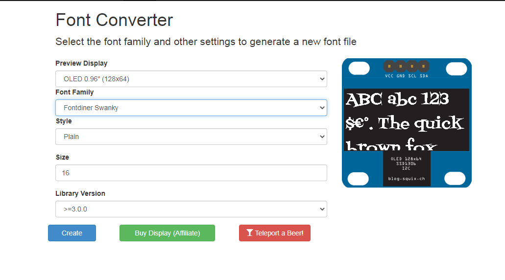
http://oleddisplay.squix.ch/#/home
Simply go to this website, choose your font size, font family, and Library Version as “Adafruit GFX Font,” and then click the “Create” button. You can see how your font will appear on the actual display on the right-hand side of this page.
The webpage will generate a hex file based on the data you pick, so to copy that font file, create a new h file in the Arduino folder of Custom fonts, call it “modified font.h” in the same folder as your code, and copy and save the generated code into it. To utilise the custom font, you only need to include the header file in your code.
#include “modified_font.h”
Then, you just need to set the font before displaying the text to apply the custom font to it.
display.setFont(&Your_Fonts_Name);
You can get the name of the font from the header file you just added to your project

Displaying custom image
To display a Bitmap Image, you must first make a 128×64 size image, which you can easily do with MS Word. Then open that image in MS Paint and alter the pixels to 128×64, and that’s it. The next step is to send that image size to an image converter website. The following is a link:
http://javl.github.io/image2cpp/


The website converts images into byte-strings, which can be used with Arduino and OLED displays. Upload the image to the website. Then select the orientation and hit the “Generate Code” button to generate the byte array by checking the “Invert picture colours” checkbox and changing the “Output code format” to “Arduino Code.” The “Preview” area displays how your image will appear on the screen.
]
OLED ADVANTAGES:
- Smaller volume
- Ultra-low power consumption
- High Contrast
- Display dot self-luminous
- Wide voltage support
- Thin and lightweight display
- No need for a backlight
- Deep black color
- Brightness and contrast are great
- Viewing angle are wider than LCD’
OLED DISADVANTAGES:
- Costly
- Short lifespan
- Water damage
- More likely to burn in
CONCLUSION:
I hope all of you had become familiar with the OLED display and also interfacing OLED with the ESP8266 NodeMCU microcontroller. Our Online store-MATHA ELECTRONICS will be back with more interesting topics.