
Buck-boost converters are a form of switching-mode power supply. It may generate a regulated DC output from a voltage source that is either higher or lower than the intended output voltage. This is especially useful in battery-powered applications where the battery voltage begins higher than the intended output but drops as the battery drains. Understanding the foundations of buck-boost converters is beneficial to every engineer.In this blog, we are discussing the buck-boost converter, operating principle, and its applications.
What is a Buck Boost Converter?
A Buck–Boost converter (also known as a chopper) is a type of DC–to–DC converter with an output voltage magnitude that is either more than or less than the input voltage magnitude. A buck-boost converter circuit includes the features of both a buck converter and a boost converter, however it has a bigger footprint than either. It works in the same way that a transformer does in AC circuits: it “steps up” the DC voltage. The buck-boost converter is similar to the flyback converter, only it employs a single inductor instead of a transformer.

Buck-boost converters are made up of two types of circuits with different topologies in which both have a large output output voltage voltage range, ranging from a voltage that is much higher (in absolute value) than the output voltage to a voltage that is close to zero. A switching power supply having a circuit similar to a buck converter or a boost converter, but with the output voltage polarity opposite the input voltage, is known as a reverse architecture. The output voltage can be varied by changing the duty cycle of the switching power crystal. A hybrid architecture that blends buck and boost converters is the second option.
The output voltage has the same electrical polarity as the input voltage and can be smaller or larger. Switches can be used instead of diodes in this type of non-inverting converter, and the buck and boost converter parts can share an inductor
A typical Buck-Boost converter is shown below.
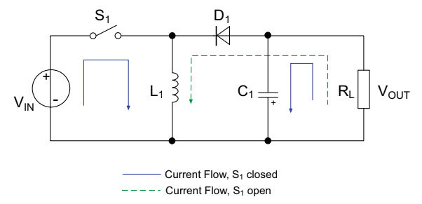
In the circuit diagram, V out is really negative in relation to the supply potential, which can make certain designs more difficult. Buck-boost converters are more expensive due to the fact that they must tolerate both a high Vin max voltage and a high input current at Vin min, but they are helpful in a wide range of applications. Buck-boost converters are frequently used in high-power LED lighting applications, such as when lead-acid batteries deliver a nominal 9-14V to a continuous 12V LED demand.
Working principle of Buck-Boost Converter
The DC to DC converter’s working process is that the inductor in the input resistance causes an unexpected change in the input current. When the switch is turned on, the inductor receives energy from the input and stores it as magnetic energy. When the switch is closed, the energy is discharged. The capacitor’s output circuit is considered to be high enough that the time constant of an RC circuit on the output stage is high. The large time constant is compared to the switching period to ensure that the steady state is a constant output voltage Vo(t) = Vo(constant) and that the load terminal is present.
Modes Of Buck Boost Converters
The Buck Boost converter has two modes of operation. The first mode is when the switch is on and conducting.
Mode I : Switch is ON, Diode is OFF

When the switch is turned on, it creates a short circuit with zero resistance to current flow. When the switch is turned on, all current flows via the switch, inductor, and back to the DC input source.
The inductor holds charge during the solid state switch is on, and when the switch is turned off, the inductor’s polarity reverses, allowing current to flow through the load, through the diode, and back to the inductor. As a result, current via the inductor continues to flow in the same direction.
Let us say the switch is on for a time TON and is off for a time TOFF. We define the time period, T, as

and the switching frequency,

Let us now define another term, the duty cycle,

Let us analyse the Buck Boost converter in steady state operation for this mode using KVL.

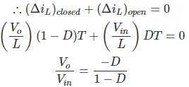
Since the switch is closed for a time TON = DT we can say that Δt = DT.

When analyzing the Buck-Boost converter, it’s important to remember that
- The inductor current is continuous, which is made possible by choosing the right L value.
- During the ON state, the inductor current rises from a value with a positive slope to a maximum value, then falls back to the initial value with a negative slope. As a result, the inductor current has no net change during a complete cycle.
Mode II : Switch is OFF, Diode is ON
In this mode the polarity of the inductor is reversed and the energy stored in the inductor is released and eventually dissipated in the load resistance, which helps to maintain current flow in the same direction through the load and step-up the output voltage because the inductor is now acting as a source alongside the input source. However, when analysing the circuit with KVL, we stick to the original conventions.
Let us now analyse the Buck Boost converter in steady state operation for Mode II using KVL.

Since the switch is open for a time

we can say that.
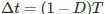
It is already established that the net change of the inductor current over any one complete cycle is zero.
We know that D varies between 0 and 1. If D > 0.5, the output voltage is larger than the input; and if D < 0.5, the output is smaller than the input. But if D = 0.5 the output voltage is equal to the input voltage.
A circuit of a Buck-Boost converter and its waveforms is shown below.
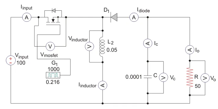
The inductance, L, is 50mH and the C is 100µF and the resistive load is 50Ω. The switching frequency is 1 kHz. The input voltage is 100 V DC and the duty cycle is 0.5.
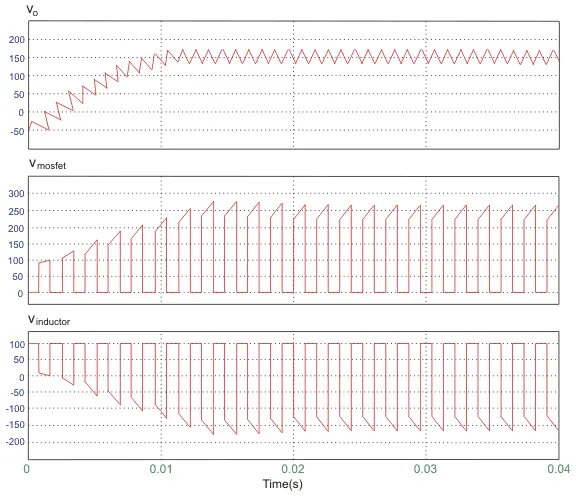
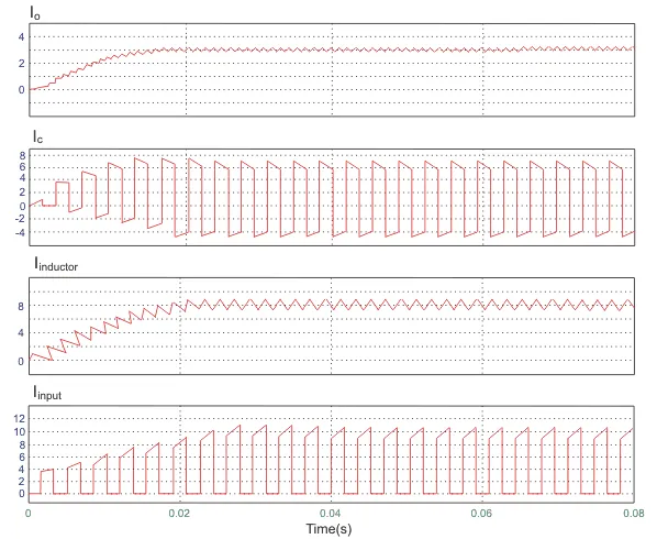
The voltage waveforms are as shown above and the current waveforms are as shown in the figure below.
Advantages of Buck Boost Converter
- It gives higher output voltage.
- Low operating duct cycle.
- Low voltage on MOSFETs
Applications of Buck boost converter
- It is used in the self regulating power supplies.
- It has consumer electronics.
- It is used in the Battery power systems.
- Adaptive control applications.
- Power amplifier applications.
CONCLUSION:
Thus, this is all about the Buck Boost Converter Circuit Working and applications. The information given in the article is the basic concept of buck boost converters.Hope you all understand this article