
Organic Light-Emitting Diode (OLED) is a technology that employs LEDs to produce light that is produced by organic molecules. These organic LEDs are utilized to make what is widely regarded as the best display panels in the world.

In this blog, we are discussing the basics of OLED, and how to Interface OLED Display with the Arduino. Here we are using SSD1306 I2C OLED Display to interface with the Arduino.
What is an OLED?
OLED stands for Organic Light Emitting Diode, and it is made up of individual image elements called pixels comprises of organic chemical compounds that emit light when an electric current is supplied between their anode and cathode. Light is emitted through the recombination of electrons and holes from the cathode and anode in this process, which is similar to that of a normal LED.

OLEDs provide for emissive displays, in which each pixel is individually controlled and generates its own light (unlike LCDs in which the light comes from a backlighting unit). OLED displays have excellent image quality, with vibrant colors, quick motion, and, most significantly, strong contrast. Specifically, “real” blacks (that cannot be achieved in LCDs due to the backlighting). Because of the simple OLED design, flexible and transparent screens are relatively easy to build.
OLED Device Structure
The basic structure of an OLED is simple: an organic emitter is sandwiched between two electrodes. Commercial OLEDs, on the other hand, utilize multiple intermediate layers, such as electron transport and blocking layers, to make efficient and long-lasting devices. Between the electrodes, the entire organic stack is inserted, and the entire structure is deposited on the substrate (glass or plastic) and the display backplane (driver electronics). Some OLED panels on the market have dozens of layers stacked on top of each other.

Interfacing an OLED(I2C) with Arduino
Components Required
- Breadboard
- SSD1306 I2C OLED Display
- USB A to B
- Arduino Uno or similar
- Jumper Cables
- Laptop
Software required
- Arduino IDE
- Library of OLED Adafruit_SSD1306
- GFX Library Adafruit
SSD1306 I2C OLED Display

The OLED module depicted in the above image is one of the most widely used on the market. There are several various versions of this module on the market, with differing resolutions, connection protocols, and pixel colors.
SSD1306 IC, a driver IC for 128×64 Dot Matrix OLED segments, is used to power these OLED modules. The SSD1306 has its own controller and can communicate via both SPI and I2C protocols. As a result, there are a variety of OLED modules on the market, some of which only support SPI communication, some that only support I2C communication, and still others that support both I2C and SPI communication. (Each module has a different number of pins.)
Since the driver, IC provides 128×64 resolution, other variations, such as 128×32, have a lower resolution. Colors such as blue, yellow, and white are supported by different modules. Some modules also allow for the use of numerous colors. To find out which colors are supported by your display module, look at the specifications.
We’re utilizing a 128×64 OLED module with 4-pin I2C connectivity, identical to the one in the image above.
Pin Description

- VCC: This is the power pin for the module. A supply of 3.3V or 5V can be provided to this pin to power the display.
- GND: This is the ground pin for the module.
- SCL and SDA: These are the serial clock and serial data pins for I2C communication.
Connection diagram
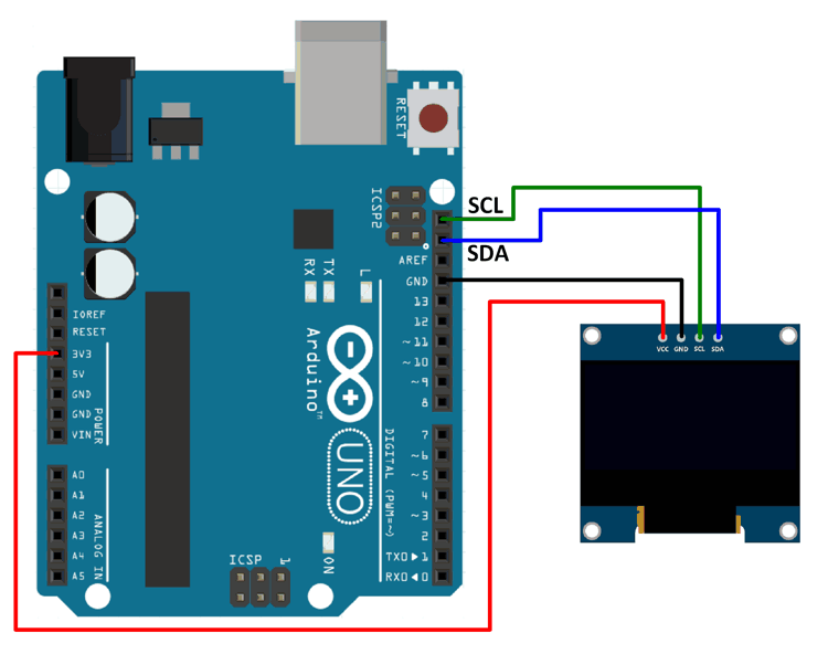
We’re utilizing Adafruit’s SSD1306 library here. This library can be found on GitHub. Only monochromatic displays are supported by this library. For the patterns, photos, and text that we will be displayed on the display, we will also require the Adafruit GFX library.
Extract these libraries and add them to the libraries folder path of Arduino IDE.
Note: Make sure you’re using the correct I2C device address. 0x3C or 0x3D are the device addresses utilized. Please use one of the following addresses. You’ll have to figure out which one is the address for your device. This address is not the device’s 8-bit address; it is the address created by the 7 bits without the read or write bits. If one of these addresses does not work, switch to the other.
Program
| #include <SPI.h> #include <Wire.h> #include <Adafruit_GFX.h> #include <Adafruit_SSD1306.h> Adafruit_SSD1306 display(-1); void setup() { // initialize with the I2C addr 0x3C display.begin(SSD1306_SWITCHCAPVCC, 0x3C); // Clear the buffer. display.clearDisplay(); // Display Text display.setTextSize(2); display.setTextColor(WHITE); display.setCursor(0,15); display.println(“Robu.in!”); display.display(); delay(1000); display.clearDisplay(); // Display Inverted Text display.setTextColor(BLACK, WHITE); // ‘inverted’ text display.setCursor(0,15); display.println(“Robu.in!”); display.display(); delay(1000); display.clearDisplay(); // Changing Font Size display.setTextColor(WHITE); display.setCursor(0,15); display.setTextSize(2); display.println(“Hello!”); display.display(); delay(2000); display.clearDisplay(); // Display Numbers display.setTextSize(2); display.setCursor(0,15); display.println(“SKU:62312”); display.display(); delay(2000); display.clearDisplay(); // Display ASCII Characters display.setCursor(0,0); display.setTextSize(3); display.write(3); display.write(3); display.write(3); display.write(3); display.write(3); display.write(3); display.write(3); display.display(); delay(2000); display.clearDisplay(); // Scroll full screen display.setCursor(0,0); display.setTextSize(1); display.println(“Made with”); display.println(“Love”); display.println(“by Apurva”); display.display(); display.startscrollright(0x00, 0x07); delay(2000); display.stopscroll(); delay(1000); display.startscrollleft(0x00, 0x07); delay(2000); display.stopscroll(); delay(1000); display.startscrolldiagright(0x00, 0x07); delay(2000); display.startscrolldiagleft(0x00, 0x07); delay(2000); display.stopscroll(); display.clearDisplay(); // Scroll part of the screen display.setCursor(0,0); display.setTextSize(1); display.println(“Robu.in”); display.println(“Follow on IG”); display.println(“Subscribe on Youtube”); display.println(“Like On Facebook”); display.display(); display.startscrollright(0x00, 0x00); } void loop() {} |
Output

Conclusion
Hope this blog helps you to understand the basics of OLED Display, and how to interface it with Arduino. We, MATHA ELECTRONICS will come back with more informative blogs.